
Decontamination and cleaning process for hydrocarbon contaminated equipment

a technology for cleaning process and hydrocarbon contaminated equipment, which is applied in the preparation of detergent mixture composition, cleaning using liquids, and cleaning hollow articles, etc., and can solve the problems of equipment out of service, system cannot be exposed to air, and facilities experience significant financial losses

Active Publication Date: 2018-03-29
USA DEBUSK LLC
View PDF3 Cites 1 Cited by
  • Summary
  • Abstract
  • Description
  • Claims
  • Application Information

AI Technical Summary

Benefits of technology

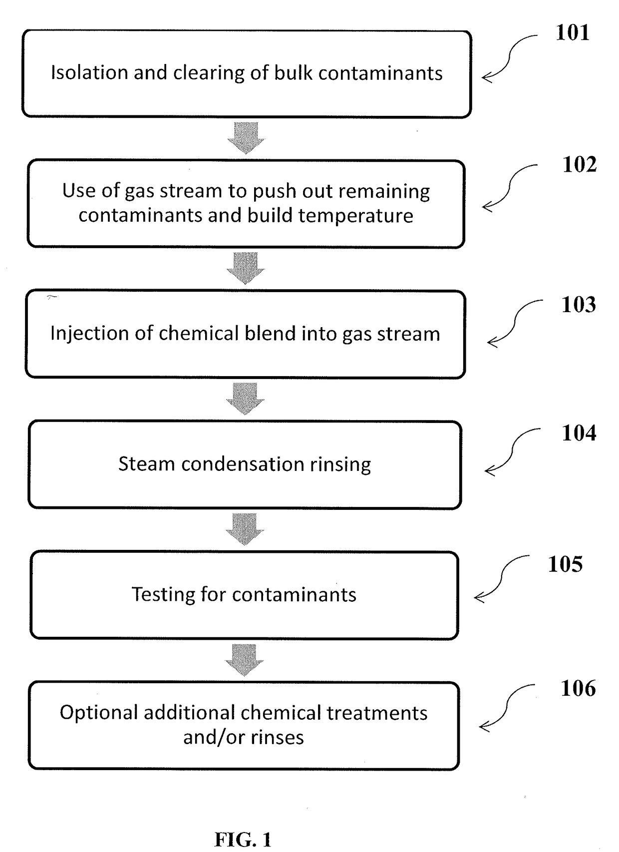
The present invention provides a process for decontaminating equipment that has been taken out of service. The process involves injecting a gas stream, such as steam, into the equipment and then injecting a mixture of aromatic solvent and surfactant. The solvent and surfactant are atomized to ensure they are dispersed throughout the equipment. The gas stream, solvent, and surfactant condense on the internal surface of the equipment to form a condensed liquid, which is then removed. The process can also include rinsing the equipment with water. The invention also provides a process for cleaning hydrocarbon-contaminated equipment by injecting steam, aromatic solvent, and surfactant, and rinsing the equipment with steam. The technical effects of the invention include improved decontamination and cleaning of equipment with reduced labor and downtime.

Problems solved by technology

The facilities experience significant financial loss for every hour that the equipment is out of service, so getting the equipment ready for maintenance as quickly as possible is desired.
While the equipment may seem empty at this point and may be under a steam or nitrogen atmosphere, the system cannot be exposed to the air, due to the noxious qualities of the vapors remaining in the equipment.
Over an extended period of time, any of these gas streams will lower the noxious vapor content of the equipment, but there are numerous limitations to this method.
For instance, this “steam-out” process requires a substantial amount of time to initially clear noxious gases, such as hydrogen sulfide (H2S), and benzene.
Steaming a vessel could take more than a week to complete.
Another downside of this process is the possibility of noxious vapors reappearing if personnel disturb any material in the equipment.
Indeed, contaminants, such as benzene, can be trapped beneath scale or other waste product and seep out at later time (e.g., when cleaning had been considered completed).
However, as with the previous method discussed above, there are deficiencies in this process.
First, the volume of effluent waste generated can be significant and difficult to treat.
Second, the time to completely treat a vessel remains long, often lasting several days.
Third, the equipment is only cleaned where it is contacted with the liquid chemical cleaner.
Much of a larger vessel may remain untreated due to poor distribution of the chemical cleaner, especially when liquid channeling occurs and with the bottom sides of equipment internals.
Finally, the aqueous chemical solutions have a limited ability to dissolve or remove heavier hydrocarbon materials that are inside the equipment.
This material may give off noxious fumes or hamper planned mechanical work or visual inspections.
This process is also faster than the previous methods discussed above, often decreasing the decontamination process by more than one day.
However, the terpene solvent steam cleaning approach is very costly.
While terpenes may have beneficial physical properties for use in the process, the raw material costs for terpenes are very high and are much more expensive than other cleaning solutions.
In particular, terpene is a volatile unsaturated hydrocarbon found in the essential oils of plants, especially conifers and citrus trees, which means that it has one or more unsaturated double bonds between the carbon atoms.
Accordingly, since terpenes and other unsaturated hydrocarbons have high reactivity and a tendency to polymerize, unsaturated compounds generally would not be expected to be present in large quantities in crude petroleum.
Thus, constant tracking of the terpene is necessary, but can be burdensome and time-consuming.
All of the above-mentioned processes have associated drawbacks and limitations that significantly hinder the speed and efficiency of the decontamination process during a turnaround.

Method used


Image

  • Decontamination and cleaning process for hydrocarbon contaminated equipment

Examples


Embodiment Construction

[0015]The present invention is directed to an improved process for the cleaning of equipment contaminated with hydrocarbon material during turnaround periods, for example, periods when the equipment is out of service. In particular, the present invention relates to a process for removing noxious gases and cleaning hydrocarbon contaminants from equipment that is taken out of service including injecting a suitable solvent into the contaminated equipment with a gas stream, such as steam, and an additive. Advantageously, the combination of the steam and the chemical blend of the suitable solvent and additive dissolves harmful hydrocarbon material and removes noxious vapors from the equipment making it safe for facilities to allow personnel to access the internal portions of machinery. Indeed, according to the present invention, the solvent and additive condense in the equipment due to the steam flow. This, in turn, allows for the cleaning solution to penetrate equipment interstices and ...


PUM


Abstract

The present invention relates to a process for removing noxious gases and cleaning hydrocarbon contaminants from equipment at a refinery, plant, or other facility during a turnaround period. The process includes injecting an aromatic solvent into the contaminated equipment with a gas stream, such as steam, and an additive. The combination of the steam and the chemical blend of solvent and additive dissolves harmful hydrocarbon material and removes noxious vapors from the equipment in a manner that is faster, more efficient, and can be performed at a significantly lower cost.

Description

FIELD OF THE INVENTION[0001]The present invention relates to improved processes for the cleaning of equipment contaminated with hydrocarbon material during turnaround periods at refineries, plants, and other facilities. The improved process decontaminates, cleans, and restores the operating efficiency of the contaminated equipment, while also allowing for faster equipment decontamination and cleaning at a significantly lower cost.BACKGROUND OF THE INVENTION[0002]Oil refineries, petrochemical plants, and other facilities that process hydrocarbons run equipment 24 hours a day, seven days a week to maximize efficiency. The goal of these facilities is to remain operational for as long as possible and to avoid downtime whenever feasible. However, regardless of continuous run times and steps taken to continue operations, all facilities must, at some point, stop operations to take the process equipment out of service for repairs, upgrades, and inspections. This activity is often called a “...

Claims


Application Information

Patent Timeline
IPC IPC(8): B08B3/08C11D3/43C11D3/02
CPCB08B3/08C11D3/02C11D3/43B08B9/00C10G75/00C11D2111/44C11D2111/20B08B2230/01B08B9/08
Inventor MONTGOMERY, BLAKE
Owner USA DEBUSK LLC
Learn More