Cool oxygen chemical gas generator

a gas generator and oxygen technology, applied in the field of chemical oxygen gas generators, can solve the problems of clogging the porous charge, affecting the efficiency of gas generators, so as to prevent the heating of the outer surfa

Active Publication Date: 2005-03-10
NEDERLANDSE ORG VOOR TOEGEPAST-NATUURWETENSCHAPPELIJK ONDERZOEK (TNO)
View PDF13 Cites 11 Cited by
  • Summary
  • Abstract
  • Description
  • Claims
  • Application Information

AI Technical Summary

Benefits of technology

Small amounts of special substances are introduced into the charge composition to: provide a self-sustaining decomposition (combustion) generating oxygen, control the reaction rate, form a heat-proof slag with a high-melting and −boiling point, and scavenge harmful contaminants (e.g. chlorine and its compounds) which may appear in small amount as a result of side reactions.
To achieve the proper burning and cooling characteristics, it is preferred that the porous material has a very high specific surface. It is important that at the substantial porosity and relatively high specific surface of the pores, a rather high charge strength is assured (the minimum compression strength is at least 0.67 MPa and the modulus of elasticity is over 50 MPa). These mechanical characteristics assure when assembling, operating and transporting the gas generator, that the charge does not deform, remains integer and doesn't crack or crumble.
Another part of this invention is a thermal protection on the oxygen generator housing to prevent heating of its outer surface during the burning of a charge.

Problems solved by technology

Therefore, these filters are much larger and heavier than would be the case if the only purpose was to filter and cleanse the oxygen.
In fact, the filters are counterproductive for mass and volume reduction.
If that were not the case, particulate material might clog the porous charge and functioning of the gas generator would be impaired.

Method used


Image

  • Cool oxygen chemical gas generator
  • Cool oxygen chemical gas generator

Examples


Embodiment Construction

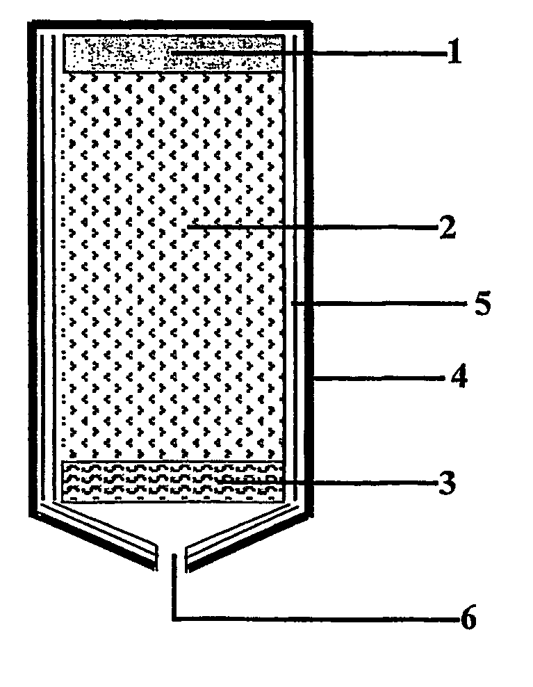
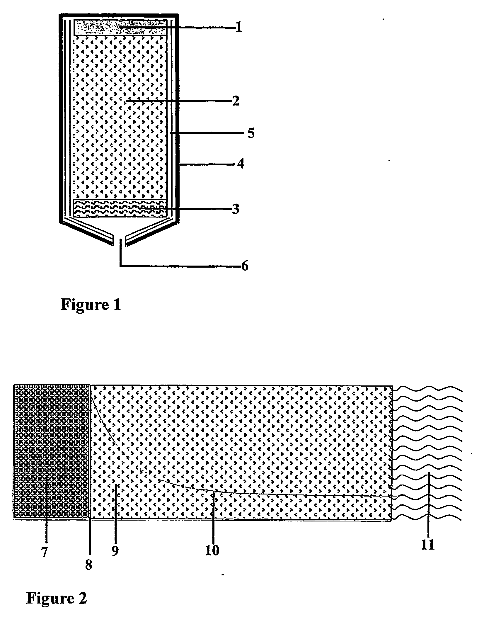
The chemical cool oxygen generator (FIG. 1) includes a housing, 4, wherein a porous charge, 2, made of the oxygen generating material is mounted. The self-sustaining decomposition (combustion) of the charge, 2, is initiated by means of the igniter, 1. The reaction starts on the charge surface adjacent to the igniter and the reaction front runs through the charge body to the opposite end in direction to the vent, 6. Under the pressure difference the oxygen generated as a result of the reaction passes through the body of the virgin porous charge, is cooled there and passes through vent, 6, to the user, or to a storage bottle.

In one of the preferred embodiments, the housing is protected from the heat of the decomposing charge by a thermal protection 5, preferably made from silica or glass fiber impregnated with the same binder as used for the charge 2. In another preferred embodiment, the charge 2 itself provides the thermal protection of the housing. In this case a layer of ˜1.5 mm...


PUM

PropertyMeasurementUnit
temperatureaaaaaaaaaa
porosityaaaaaaaaaa
porosityaaaaaaaaaa

Abstract

The present invention is directed to a chemical oxygen generator to produce cool oxygen gas comprising: a. a charge housing, b. a solid but porous charge contained in the said housing, the charge being made of a chemical mixture that generates oxygen upon decomposition and that will undergo a self-sustained exothermal decomposition after initiation, the said charge containing at most 3.0 wt. % of binder material, the said porous charge allows the generated oxygen to pass through the charge without damaging the virgin material and without creating volumetric burning, the said charge is mounted in the housing in such a way that the generated oxygen passes through the charge and under the pressure difference flows from the moving decomposition front towards the vent, c. an ignition device mounted at one end of the cartridge in such a way that it is capable to initiate a self-sustained decomposition of the charge at the charge surface adjacent to the initiator, d. one or more vents mounted in such a way that the generated oxygen that has passed through the generating porous charge leave the gas generator through the said vents.

Description

FIELD OF THE INVENTION This invention relates to a chemical oxygen gas generator. BACKGROUND OF THE INVENTION Chemical oxygen (pyrotechnic) gas generators have been developed and used already for long periods. Self-controlled, continuously ready to operate for many years without any verification tests, easy activation from low-power electric sources, small size, safe, a rather high yield of oxygen on a per-unit volume and unit mass and a number of other advantages make them irreplaceable in case of emergencies and in accidents. They are used and applied, for instance, for the emergency supply of oxygen to the passengers in aircraft in case of cabin depressurization, in submarines if the other emergency oxygen supply systems fail, in space stations in case of emergency if the basic oxygen supply systems fail, and in many other conceivable emergency cases. A typical example of the use of oxygen generators on-board aircraft is presented in U.S. Pat. No. 4,840,171. An operational app...

Claims


Application Information

Patent Timeline
Patent Type & Authority Applications(United States)
IPC IPC(8): A62B21/00B01D53/62C01B13/02C06D5/06
CPCY10S280/07A62B21/00B01D2257/502C06D5/06Y02C10/04C01B13/0218B01D53/62C01B13/0211Y02C20/40
Inventor ZHARKOV, ALEXANDR SERGEEVICHSHANDAKOV, VLADIMIR ALEKSEEVICHALEXANDROVICH, PILYUGIN LEONIDVAN DEN BERG, RONALD PETER
Owner NEDERLANDSE ORG VOOR TOEGEPAST-NATUURWETENSCHAPPELIJK ONDERZOEK (TNO)
Why Eureka
Try Eureka