Airlift Reactor Assembly with Helical Sieve Plate

a technology of airlift reactor and sieve plate, which is applied in the direction of bioreactor/fermenter specific use, chemical/physical/physicochemical process, after-treatment of biomass, etc., can solve the problems of reducing the effective operation range of airlift reactor, adverse to efficient gas-liquid mass transfer, and reducing the size of the bubbles , to achieve the effect of enhancing radial and axial micro-mixing, reducing the size of the bubble, and reducing the bubbl

Inactive Publication Date: 2018-05-03
JIANGNAN UNIV
View PDF4 Cites 16 Cited by
  • Summary
  • Abstract
  • Description
  • Claims
  • Application Information

AI Technical Summary

Benefits of technology

[0048](1) The helical sieve plate according to the present invention is mounted in the riser section of the airlift reactor to break the rising bubbles and form a helical passage. When bubbles are ejected from the gas sparger, a part of the gas-liquid flow moves upward, and the rising large bubbles are broken by the sieve pores on the sieve plate into small bubbles, thereby significantly reducing the size of the bubbles and improving the gas-liquid mass transfer efficiency. The other part of the gas-liquid flow moves upward along the helical direction of the helical sieve plate. The two parts of fluids interact with each other to form a cross-current flow and a turbulent flow, which enhances the radial and axial micro-mixing, helps to prevent bubble coalescence and reduces the bubble size. Compared with the horizontal sieve plate, the fluid resistance of the rising flow is smaller, the air blocking and slug flow are not easy to occur, and the effective operating range of the reactor is widened. The helical passage enables the gas-liquid fluid to form a circulation, thereby promoting the macroscopic mixing. The installation of the helical sieve plate also improves the gas-liquid mass transfer performance, i.e., significantly improves the gas holdup and volumetric oxygen transfer coefficient.
[0049](2) The appropriate free area ratio of the helical sieve plate prevents bubbles from coalescing into a large bubble and ensures excellent gas-liquid mass transfer efficiency.
[0050](3) The baffle according to the present invention is mounted at the inlet of the downcomer section. After a two/three-phase flow ascends to the two/three-phase separation zone, the flow w

Problems solved by technology

As bubbles are easy to coalesce in the riser section in the airlift reactor in commercial application and the adjustment range of operating parameters is narrow, the operation flexibility of the reactor is limited.
However, the installation of horizontal wire mesh or sieve plate in the riser section will reduce the effective operation range of the airlift reactor.
When the air flow rate is too

Method used


Image

  • Airlift Reactor Assembly with Helical Sieve Plate
  • Airlift Reactor Assembly with Helical Sieve Plate
  • Airlift Reactor Assembly with Helical Sieve Plate

Examples


example 1

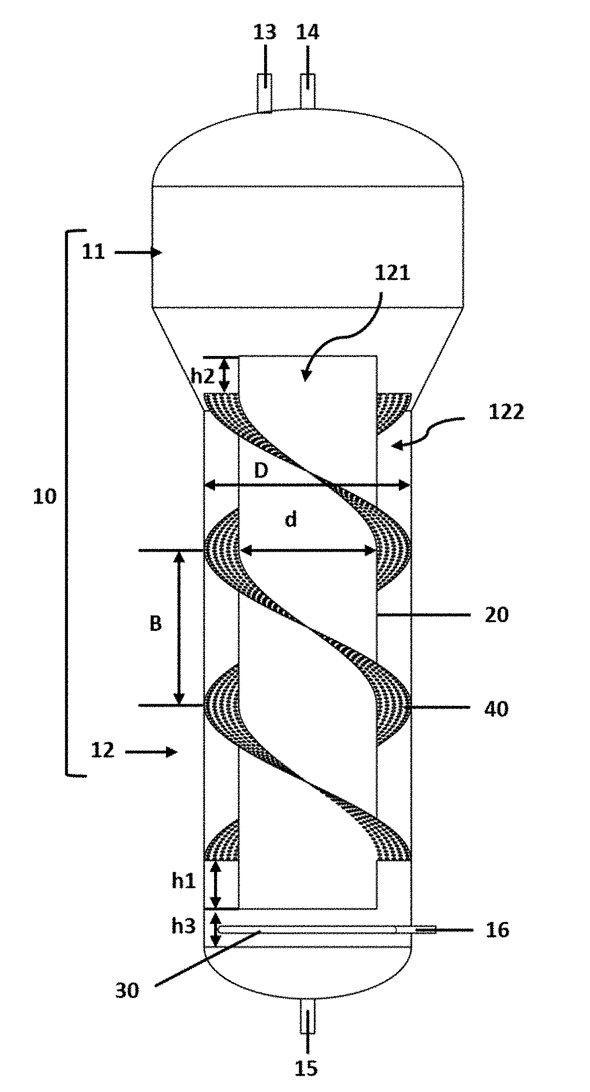
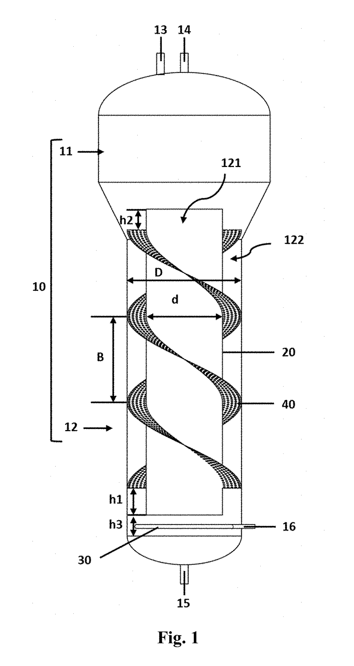
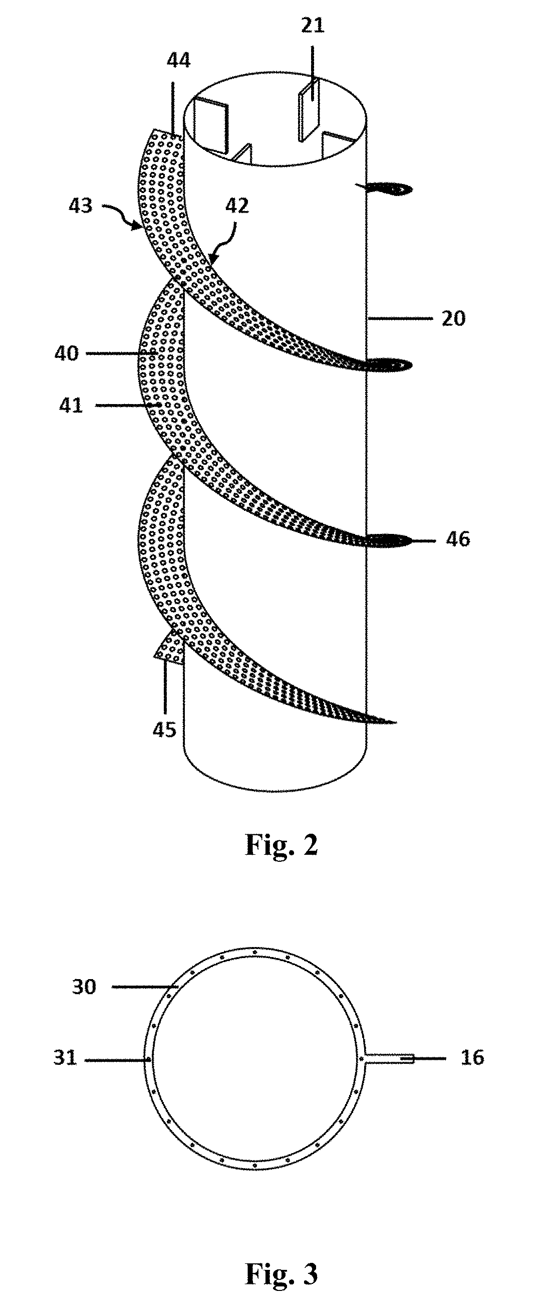
[0064]Referring to FIG. 1 to FIG. 3, an airlift reactor with a helical sieve plate is used for gas-liquid reaction as shown in the legends in the figures. The airlift reactor comprises a reaction tank 10, the internal space of the reaction tank 10 is divided into a gas-liquid mixing zone 12 located on the lower side and a gas-liquid separation zone 11 located on the upper side. The gas-liquid mixing zone 12 is provided with a draft tube 20 and a gas sparger 30 on upper and lower portions therein. The draft tube 20 and the reaction tank 10 are coaxially arranged to divide the gas-liquid mixing zone 12 into a cylindrical downcomer section 121 located inside of the draft tube 20 and an annular riser section 122 located outside the draft tube 20, and the gas sparger 30 introduces air into the annular riser section 122. The airlift reactor also comprises a helical sieve plate 40 mounted in the round riser section 122, the body of the helical sieve plate 40 is helical upwards, and sieve m...

example 2

[0087]Referring to FIG. 4 to FIG. 6, an airlift reactor with a helical sieve plate is used for gas-liquid reaction as shown in the legends in the figures. The airlift reactor comprises a reaction tank 10, and the internal space of the reaction tank 10 is divided into a gas-liquid mixing zone 12 located on the lower side and a gas-liquid separation zone 11 located on the upper side. The gas-liquid mixing zone 12 is provided with a draft tube 20 in the upper side and a gas sparger 30 in the lower side therein. The draft tube 20 and the reaction tank 10 are coaxially arranged to divide the gas-liquid mixing zone 12 into a cylindrical downcomer section 123 located inside of the draft tube 20 and an annular riser section 124 located outside the draft tube 20, and the gas sparger 30 introduces air into the annular riser section 123. The airlift reactor also comprises a helical sieve plate 40 mounted in the cylindrical riser section 123, the body of the helical sieve plate 40 is helical up...

example 3

[0111]The remaining is the same as the embodiment 1. The difference is that the airlift reactor in the present embodiment is used for aerobic cultivation of microorganisms, animal cells and plant cells. The ratio of air flow (m3 / min) to culture solution volume (m3) is 0.1 to 3. When the reactor is a small reactor, the ratio is biased to the upper limit. During medium-scale and large-scale reaction, the ratio is biased to the lower limit, but the specific operating parameters should be determined based on actual oxygen uptake rate requirements of the microorganisms. The operating pressure (gauge pressure) is generally from 0.2 to 2.0 atm.

[0112]In one embodiment, the reaction tank, the draft tube and the helical sieve plate are made of transparent materials to be suitable for photoreaction.


PUM


Abstract

The present invention discloses an airlift reactor assembly with a helical sieve plate, comprising a reaction tank, wherein a draft tube and a gas sparger are assembled in the reaction tank, the gas sparger is arranged just below an riser section of the draft tube, a helical sieve plate is arranged in the riser section of the draft tube, and a body of the helical sieve plate is helical upwards to guide a part of two/three-phase flow in the riser section, and the body of the helical sieve plate is provided with a plurality of sieve meshes to guide the remaining two/three-phase go through the helical sieve plate in the riser section and to break bubbles. The present invention gives consideration to both macroscopic mixing and microscopic mixing processes. In addition to driving liquid to circularly flow by using ejected gas, the helical sieve plate can be used for breaking large bubbles into small bubbles thereby effectively preventing the bubbles from coalescing, increasing gas holdup and increasing a volumetric oxygen transfer coefficient.

Description

CROSS-REFERENCES AND RELATED APPLICATIONS[0001]This application claims the benefit of priority to Chinese Application No. 201610956295.9, entitled “Airlift Reactor Assembly with Helical Sieve Plate”, filed Oct. 28, 2016, which is herein incorporated by reference in its entirety.BACKGROUND OF THE INVENTIONField of the Invention[0002]The present invention relates to the fields of bioengineering and environmental engineering, and in particular to an airlift reactor assembly with helical sieve plate.Description of the Related Art[0003]Gas-liquid dispersion and mixing are widely used in aerobic fermentation, biological aeration, photoreaction of plant cells and algae cells, and other process units. At present, the reactors capable of implementing the gas-liquid mixing and dispersion mainly include (1) bubble column reactor; (2) airlift reactor; (3) stirred tank reactor; and (4) mixing system based on rotary nozzles.[0004]Since the 1970s, many engineers began to study the bubble column re...

Claims


Application Information

Patent Timeline
IPC IPC(8): C12M1/00B01J8/08B01J19/24B01J10/00C12M1/08
CPCC12M29/08B01J8/08B01J19/24B01J10/002C12M23/22C12M27/20C12M27/24B01J2208/00884B01J2219/24C12M21/02C12M27/22C12M41/02C12M41/22B01J4/004B01J8/10B01J8/222B01J19/006B01J19/0066B01J19/20B01J19/2405B01J2219/00094B01J2219/00768B01J2219/00772B01J2219/185B01J2219/1943
Inventor ZHENG, ZHIYONGCHEN, YUQIZHAN, XIAOBEIGAO, MINJIE
Owner JIANGNAN UNIV
Why Eureka
Try Eureka