Method for preparing a bonded type perovskite solar cell

Active Publication Date: 2018-05-03
HYUNDAI MOTOR CO LTD +1
View PDF2 Cites 8 Cited by
  • Summary
  • Abstract
  • Description
  • Claims
  • Application Information

AI Technical Summary

Benefits of technology

[0033]Since the present disclosure is a non-deposition preparing method for a perovskite solar cell without using expensive equipment, processing costs may be significantly lowered. Accordingly, price competitiveness in the market may be great

Problems solved by technology
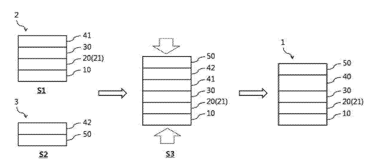
In addition, due to an increase in components mounted on the vehicle, the power consumption of the vehicle is gradually rising.
However, in the case of using a large-capacity battery, the weight of the vehicle body itself is increased, and thus fuel efficiency may be decreased.
However, these methods are preparing methods for the p

Method used


Image

  • Method for preparing a bonded type perovskite solar cell
  • Method for preparing a bonded type perovskite solar cell
  • Method for preparing a bonded type perovskite solar cell

Examples


Example

Example 1

(1) Forming of First Substrate

[0099]1) Preparing transparent electrode: Fluorine tin oxide (FTO, TEC8) doped with fluorine was cut with 2.5 cm×2.5 cm and the FTO was partially removed by etching an end part.

[0100]2) Forming electron transport layer (blocking electron transport layer): A titanium acetylacetonateethanol (a volume ratio of 1 / 9) solution was sprayed on a transparent electrode heated at 450° C. several times to form a titanium dioxide thin film with a thickness of about 50 nm.

[0101]3) Forming light absorbing layer: 10 volume % of a HI aqueous solution was put in 40 wt % of a CH3NH3PbI3 (perovskite) / dimethyl formamide solution and then the solution was dropped on the electron transport layer and spin-coated at about 3,000 RPM for 200 seconds to form a light absorbing layer.

[0102]4) Forming first hole transport layer. A solution including poly-3-hexythiophene (P3HT) as a hole conductor, dichlorobenzene as a first solvent, Li-bis(trifluoromethanesulfonyl)imide (Li-...

Example

Example 2

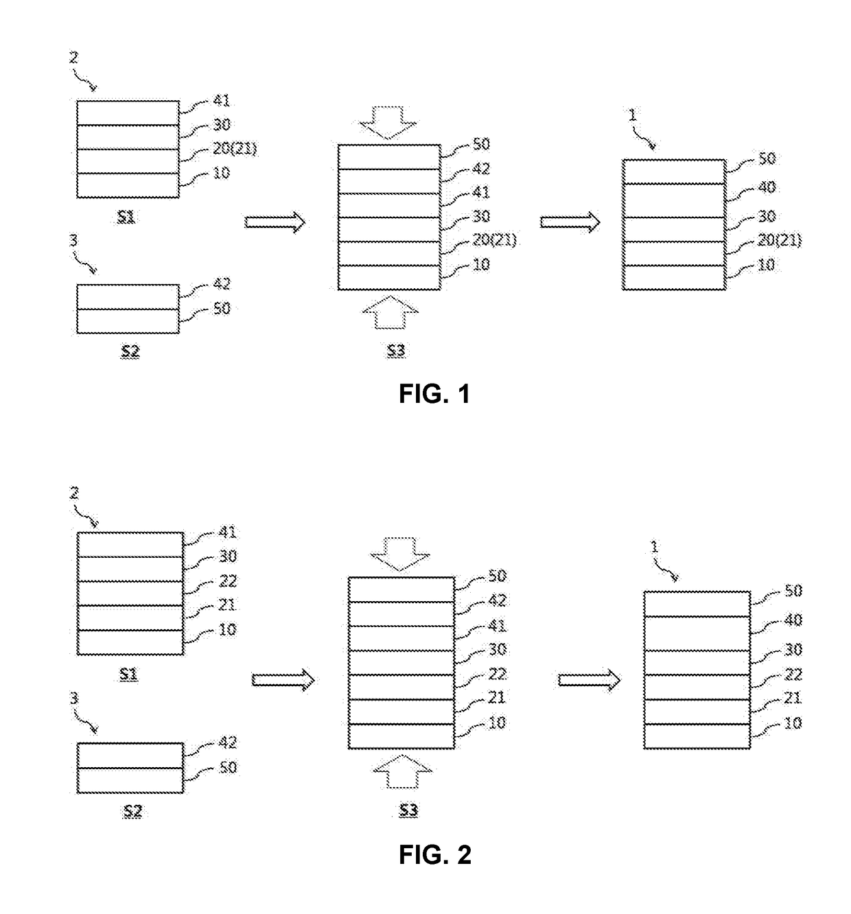
[0106]Except for forming the porous electron transport layer below after forming the blocking electron transport layer in the first substrate forming act in Example 1, the bonded type perovskite solar cell was prepared by the same method as Example 1.

[0107]Forming porous electron transport layer: A titanium dioxide paste (diSol: 18NR-T) diluted at a level of 20 nm was spin-coated on the blocking electron transport layer to form a porous electron transport layer with a thickness of about 200 nm. Thereafter, strength of the porous electron transport layer was enhanced by heating at 500° C. for 1 hr. Further, the first substrate (the porous electron transport layer / the blocking electron transport layer / the transparent electrode) was deposited in 20 mM of a tetrachloro-titanium dioxide aqueous solution at 60° C. for about 1 hr, washed with deionized water and ethanol and dried, and heated again at 500° C. for 30 minutes.

Example

Example 3

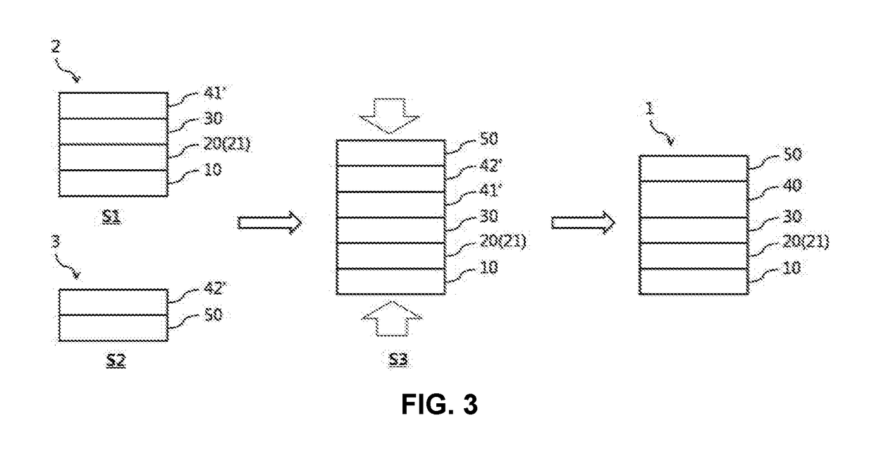
[0108]Unlike Example 1, a bonded type perovskite solar cell was prepared by using the second hole transport layer as a bonding medium of the first substrate and the second substrate. A difference from Example 1 was as follows and otherwise, the bonded type perovskite solar cell was prepared by the same method as Example 1.

[0109]Forming first hole transport layer: A solution including poly-3-hexylthiophene (P3HT) as a hole conductor, toluene as a first solvent, Li-bis(trifluoromethanesulfonyl)imide (Li-TFSI) as a lithium salt, and t-butylpyridine as an additive was dropped on the light absorbing layer and spin-coated at about 3,000 RPM for 60 seconds to form a first hole transport layer.

[0110]Forming second hole transport layer A solution including poly-3-hexylthiophene (P3HT) as a hole conductor, dichlorobenzene as a second solvent, Li-bis(trifluoromethanesulfonyl)imide (Li-TFSI) as a lithium salt, and t-butylpyridine as an additive was dropped on the opposing electrode and...


PUM

PropertyMeasurementUnit
Temperatureaaaaaaaaaa
Timeaaaaaaaaaa

Abstract

A method for preparing a perovskite solar cell by a non-deposition method is provided. Particularly, the method includes preparing a first substrate by forming a hole transport layer on a light absorbing layer in a semi-dried state and pressurizing and drying a second substrate including an opposing electrode to the first substrate.

Description

CROSS-REFERENCE TO RELATED APPLICATION[0001]This application claims under 35 U.S.C. § 119(a) the benefit of Korean Patent Application No. 10-2016-0145867, filed on Nov. 3, 2016, the entire contents of which are incorporated herein by reference.BACKGROUND(a) Technical Field[0002]The present disclosure relates to a method for preparing a perovskite solar cell by a non-deposition method.(b) Background Art[0003]Recently, as regulation for carbon dioxide emissions has been reinforced and an interest in fuel efficiency of vehicles is increased, the environment-friendly vehicle market has been expanded. In addition, due to an increase in components mounted on the vehicle, the power consumption of the vehicle is gradually rising.[0004]As a method for supplying additional power to the vehicle, a method of supplying the power by using a battery having a larger capacity or producing self-power from the frame of the vehicle may be considered. However, in the case of using a large-capacity batte...

Claims


Application Information

Patent Timeline
IPC IPC(8): H01G9/20H01G9/00H01L51/44H01L51/42H01L51/00
CPCH01G9/2009H01G9/0029H01L51/442H01L51/0035H01L51/0007H01L51/0077H01L51/0036H01L51/4213H10K71/15H10K71/12H10K30/151H10K30/10Y02E10/549Y02E10/542H10K71/50H10K85/00H10K85/50H01B1/22H01L31/02168H01L31/022425H01L31/022466H01L31/18H01L31/1884Y02E10/50H10K30/82H10K85/30H10K85/111H10K85/113
Inventor KIM, SOLSONG, MI YEONKIM, SANG HAKLEE, EUN YEONGEO, MOON JUNGIM, SANG HYUKHAN, HYE JI
Owner HYUNDAI MOTOR CO LTD
Why Eureka
Try Eureka