Retroreflective, elongated, filamentous product, process for making the same, uses thereof and products made therefrom

a technology of retroreflective and filamentous products, applied in the field of yarns, can solve the problems of difficult weaving of filament into textile products, relatively complex system, and difficulty in weaving through the method

Inactive Publication Date: 2018-05-10
C R Y SAS +1
View PDF6 Cites 8 Cited by
  • Summary
  • Abstract
  • Description
  • Claims
  • Application Information

AI Technical Summary

Benefits of technology

[0002]One common technique for providing retroreflective properties in a textile material, e.g. a fabric or garment, involves, for example, printing on, or applying high refractive index microparticles, e.g. microspheres, to the textile. The glass beads generally partially embedded from 30% to 50% in a polymer layer. If these microspheres, or microbeads, have their embedded halves coated with metallic material, for example, aluminium, their ability to reflect light increases dramatically, in the region of between twenty to fifty-fold. When incident light hits the beads, it can enter the bead via an uncovered area, and then either pass through the bead or hit a metallic coated area from within the inside of the bead, to be reflected back out again. This backscattering, or reflectance, is generally distributed under any possible scattering angle. However this reflection can be oriented quite precisely into the direction of the incoming light provided an accurate choice of the refractive index of the microspheres. This particular ability to return light in the direction of an incoming beam, called retroreflection, is currently used in the high visibility clothing industry, either for safety of workers during the night or simply to provide fashionable effects.
[0009]In a second embodiment of WO2007054457, the wire core was extrusion coated with a clear PET as the first coating layer. Silver coated beads, obtained by full metallization, were stuck into the warm polymer coating using a fluidised bed. The silver areas that were not covered in polymer coating were dissolved by treatment with hydrogen peroxide acetic acid mixture. Subsequently, a polyethylene passivation layer was dip coated onto the wire product. It should be noted that creating reflective beads by full metallization, followed by partial demetallisation, is a very lengthy, and complex process.
[0013]Another disadvantage of the known web transfer carrier material process described and known from the prior art above is that of residues from the web carrier material being transferred over during detachment of the hemi-metallised beads. This coupled with the beads' bimodal nature, reduces bead fluidity in the bead application reservoir and transport apparatus, and has a negative influence on the ability to carry out continuous all-in-one processing.SUMMARY OF THE INVENTION
[0015]Accordingly, the applicants have found that the problems of the prior art can be solved, and numerous advantages obtained in so doing, by providing a retroreflective, elongated, filamentous product, comprising
[0023]the product according to the invention can use standard unmirrored or uncoated glass microbeads as refractive microparticles available generally on the market, thereby totally avoiding the issues and disadvantages of acid etch removal of mirrored surfaces;
[0025]it exhibits flexibility and mechanical toughness due to encapsulation of a rear reflective coating between several polymer layers, avoiding any issues of adhesion failures between a metal surface and a glass-like surface of the microparticles, even under high friction and high speed processing, such as weaving or knitting;

Problems solved by technology

Such a system is both relatively complex, in that it requires the printed pattern to be designed beforehand and applied to the carrier transfer web, and additionally is only feasible for application to a pre-manufactured transformed and pre-prepared textile surface, such as a fabric, weft, web, etc, as the transfer method requires heat activation to release the microspheres from the carrier transfer web.
The above described solution is inappropriate when attempting to manufacture a yarn or thread that has the required retroreflective properties.
Objectively, this is yet again a fairly complicated process involving assembly of two laminated layers, one of which comprises the retroreflective beads or microspheres, and then slitting and re-assembling the slitted material as a twisted yarn or filament, with the result that said filament is only retroreflective to the extent that the microspheres face outwards and can receive incident light at an angle permitting adequate reflection.
Additionally, the filament produced by the method described in this patent may be difficult to weave into textile products.
It should be noted that creating reflective beads by full metallization, followed by partial demetallisation, is a very lengthy, and complex process.
Such techniques do not guarantee correct orientation of the beads.
It should, however, be noted that even uniform orientation does not appear to be considered efficient enough for the textile industry, as any weaving process would necessarily randomize the global orientation of the beads on the yarn.
Orientational randomisation is a major problem when using pre-prepared hemispherically metallised microbeads because randomisation of bead hemispheres leads to dramatic loss in retroreflection.
The other major drawback of pre-metallized beads is surface heterogeneity.
The bimodal nature of the bead surface leads to adhesion failures unless the coating in which the microbeads are embedded is optimized for both the aluminised and the glass-like halves.
Another disadvantage of the known web transfer carrier material process described and known from the prior art above is that of residues from the web carrier material being transferred over during detachment of the hemi-metallised beads.
This coupled with the beads' bimodal nature, reduces bead fluidity in the bead application reservoir and transport apparatus, and has a negative influence on the ability to carry out continuous all-in-one processing.

Method used


Image

  • Retroreflective, elongated, filamentous product, process for making the same, uses thereof and products made therefrom
  • Retroreflective, elongated, filamentous product, process for making the same, uses thereof and products made therefrom
  • Retroreflective, elongated, filamentous product, process for making the same, uses thereof and products made therefrom

Examples


example 1

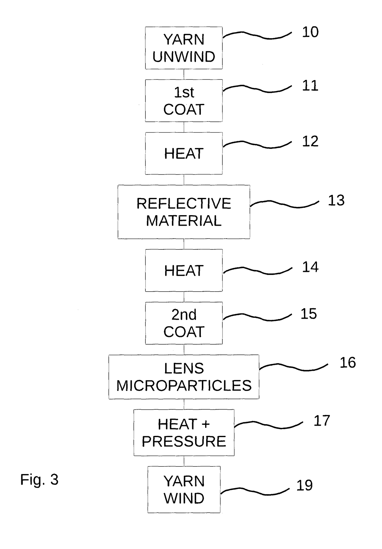
[0107]A high tenacity PA66 multifilament yarn of 110 dTex was drawn (10) at 20 m / min with a constant tension of 20 cN into a first vessel containing a crosslinkable formulation (11) as indicated in Table 1.1, and then dried in an infrared oven (12) at no more than 110° C. degrees for 20 seconds. The formulation of Table 1.1 was applied to the core yarn by total immersion of the yarn in a crosslinkable formulation bath, drawing it through the bath via a convoluted yarn path. This enabled the crosslinkable formulation to be applied between the filaments and onto the yarn surface, thereby improving adhesion and homogeneity of the formulation. The thus impregnated yarn was then passed over the surface of a motorized rotary roller, comprising one or more grooves provided in the surface of the roller, for example, by engraving, the grooves being aligned along the direction of travel of the yarn. The motorized rotary roller had a linear speed of 0.9 metres / min, and the groove or grooves a ...

coloured yarn example 1

[0128]In a different embodiment of Example 1, a load of 15 parts per hundred of the blue pigment, C.I. P.Blue 15:3 with 46% dry content, was added only to the second polymer matrix primer layer formulation in Table 1.3. The yarn was manufactured exactly as for the “open lens” example above, before and after application of the second polymer matrix primer layer. Yarn linear mass density and diameter were unchanged. The weight fractions scale up appropriately in the second polymer matrix primer layer. Since the mass ratio between the primer layer and the first polymer matrix layer is around 5 / 95, pigment contribution is less than 0.5% in the coatings, and negligible in total. The yarn had an intense blue colour under diffuse illumination. RA dropped down to 50 cd / lux / m2 for the yarn wrapped around a flat spool, which is 66% of the value observed for the unpigmented yarn.

[0129]A careful positioning of the pigmented layer, in this case behind the refractive microparticles, and yet still...

example 2

[0131]The PA66 110 dtex high-tenacity yarn was processed as for Example 1 until just before application of the second polymer matrix primer layer. The coated and dried yarn entered the vessel containing the second polymer matrix primer layer formulation as defined in Table 2.1.

TABLE 2.1second polymer matrix primer layer formulation for embedded microparticleretroreflective yarnNameDescription / usageParts per hundred (phr)Witcobond 737 (Baxenden Chem.Polyurethane dispersion adhesive100LTD.)(solid content 40%)Water (Deionized)Diluent20Trixene AQUA BI 201Blocked Isocyanate Crosslinker3Acusol 820 (DOW Europe GmbH)Thickener0.5BYK 093 (BYK Additives,Defoamer0.4ALTANA Group)BYK 349 (BYK Additives,Wetting agent0.2ALTANA Group)Gamma-Adhesion promoter1glycidoxypropyltrimethoxysilaneAmmonium hydroxide (as 5% NH3pH modifying agentQuantum sufficit for pH >7solution in water)

[0132]The primer layer wet content on the yarn was calibrated via the same applicator system with motorized rotary roller an...


PUM

PropertyMeasurementUnit
thicknessaaaaaaaaaa
thicknessaaaaaaaaaa
thicknessaaaaaaaaaa

Abstract

The present invention relates to a retroreflective, elongated, filamentous product, comprising a core of non-metallic filamentous material; a first polymer matrix layer comprising a polymer resin, located around an outer peripheral surface of, and penetrating into, the core of non / metallic filamentous material; a reflective material located on an outer peripheral surface of said first polymer matrix layer; a second polymer matrix layer comprising a polymer resin, forming a primer layer on top of said reflective material; and a plurality of refractive microparticles distributed in said second polymer matrix primer layer, wherein said plurality of refractive microparticles is partially embedded in said second polymer matrix primer layer. A process for making the product and uses thereof are also disclosed.

Description

[0001]The present invention relates to retroreflective technology for use in, on or with textile materials, and more particularly to yarns which have retroreflective properties.[0002]One common technique for providing retroreflective properties in a textile material, e.g. a fabric or garment, involves, for example, printing on, or applying high refractive index microparticles, e.g. microspheres, to the textile. The glass beads generally partially embedded from 30% to 50% in a polymer layer. If these microspheres, or microbeads, have their embedded halves coated with metallic material, for example, aluminium, their ability to reflect light increases dramatically, in the region of between twenty to fifty-fold. When incident light hits the beads, it can enter the bead via an uncovered area, and then either pass through the bead or hit a metallic coated area from within the inside of the bead, to be reflected back out again. This backscattering, or reflectance, is generally distributed ...

Claims


Application Information

Patent Timeline
Patent Type & Authority Applications(United States)
IPC IPC(8): D06M11/83D06M15/564D06P1/00D02G3/36D06Q1/10D02G3/34D02G3/18G02B5/128
CPCD06M11/83D06M15/564D06P1/0012D02G3/36D06Q1/10D02G3/346D02G3/187G02B5/128D06M2101/34D10B2401/20D06Q1/12D07B1/148D06M23/08D07B2201/2087D07B2201/2088D07B2201/2094D02G3/185D02G3/441C03C12/02
Inventor NOWAK, PASCALBOUCHET, ANNENIGRO, BRUNOBONVENTRE, FRANCESCA
Owner C R Y SAS
Why Eureka
Try Eureka