Moving injection gravity drainage for heavy oil recovery
a gravity drainage and heavy oil technology, applied in the field of subterranean hydrocarbon recovery, can solve the problems of low mobility, or even no mobility, in the reservoir under natural conditions, reduce the variability of the flux of injected steam in the sagd, and achieve high total oil recovery factors, reduce air-oil ratios, and high oil production rates
- Summary
- Abstract
- Description
- Claims
- Application Information
AI Technical Summary
Benefits of technology
Problems solved by technology
Method used
Image
Examples
example 1
eous Reservoir Simulations
[0076]The rate of heavy oil production and cumulative oil recovery using a method for recovering petroleum from a hydrocarbon-bearing subterranean formation in accordance with an embodiment of the invention has been modeled in computer simulations and compared / contrasted with the THAI and CAGD processes in a three dimensional model of a Kerrobert oil sands formation with reservoir dimensions of 250 metres by 30 metres by 30 metres, with 5 metre grid blocks. Model parameters are shown in Table 4, below.
[0077]In this Example, the MIGD process is simulated with a single injection point in the horizontal injection well, which is swept through the oil reservoir.
[0078]Reservoir heterogeneity is modelled by randomly assigning a porosity of between 10% and 70% to each grid block cell, while keeping the average reservoir porosity of 32%. The distribution of porosity in the reservoir is not a normal distribution and has a longer tail of smaller porosities than given ...
example 2
nt MIGD Simulations
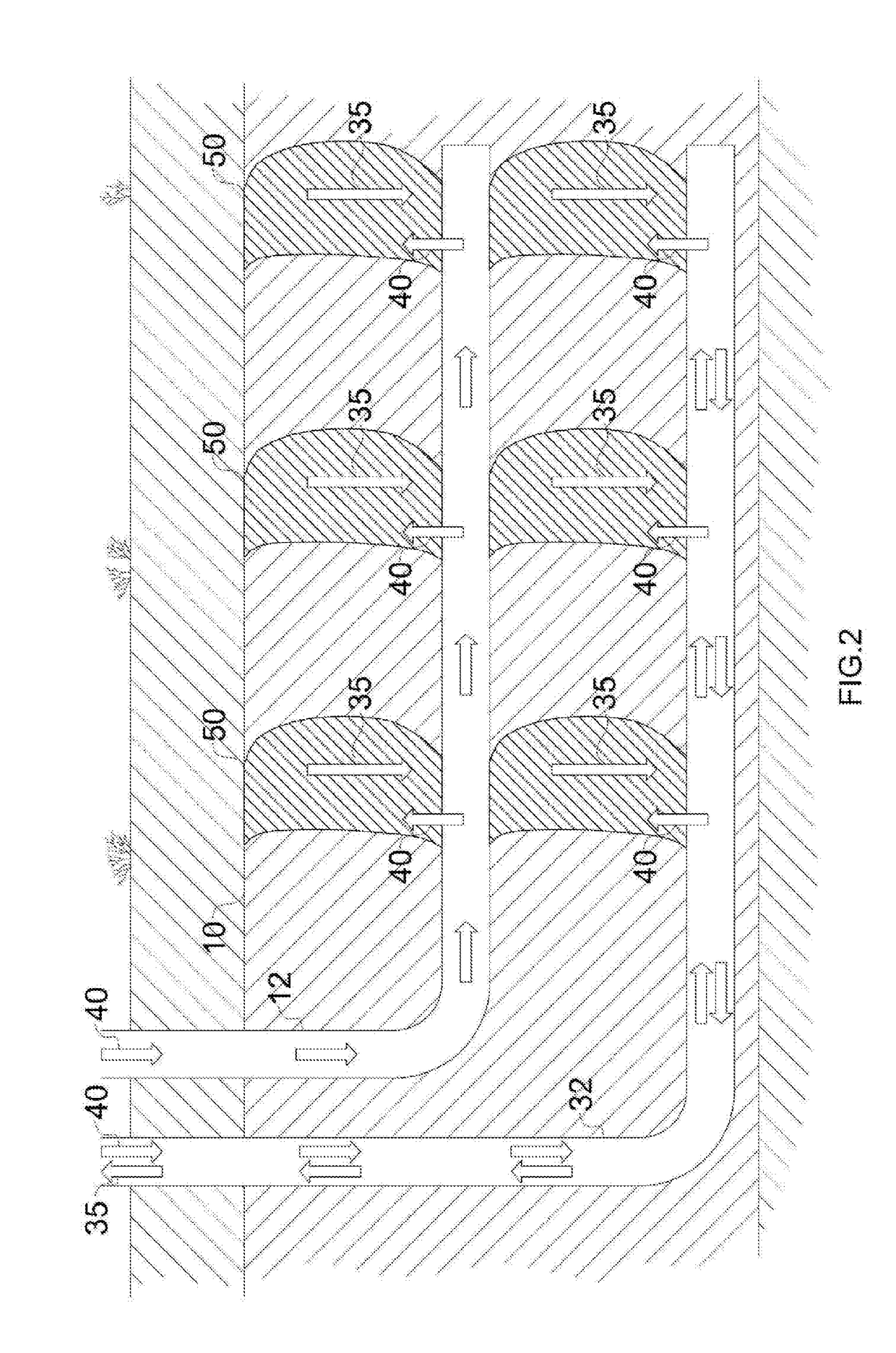
[0082]A detailed simulation of the invention has been performed to demonstrate the effectiveness of the technique for multi-point air injection, to achieve higher oil production per injection / production well pair. The simulation uses three injection points on the horizontal well by way of demonstration, however it is understood that more or less points can be utilised with the present invention.
[0083]Table 6 provides the geometrical parameters of the selected reservoir, while Table 7 provides the physical parameters. For simulation, the reservoir properties were considered to be homogeneous.
[0084]The simulations were conducted using grid blocks of size 1 metre height, 2 metres width and 2 metres length. Earlier sensitivity studies (not reported) showed that these grid block sizes provided the best compromise between computational speed and model resolution for this Example.
TABLE 6Reservoir Geometrical ParametersParameterUnitsValueTVD to top of oil paym760Oil pay t...
example 3
Modelling Sensitivities
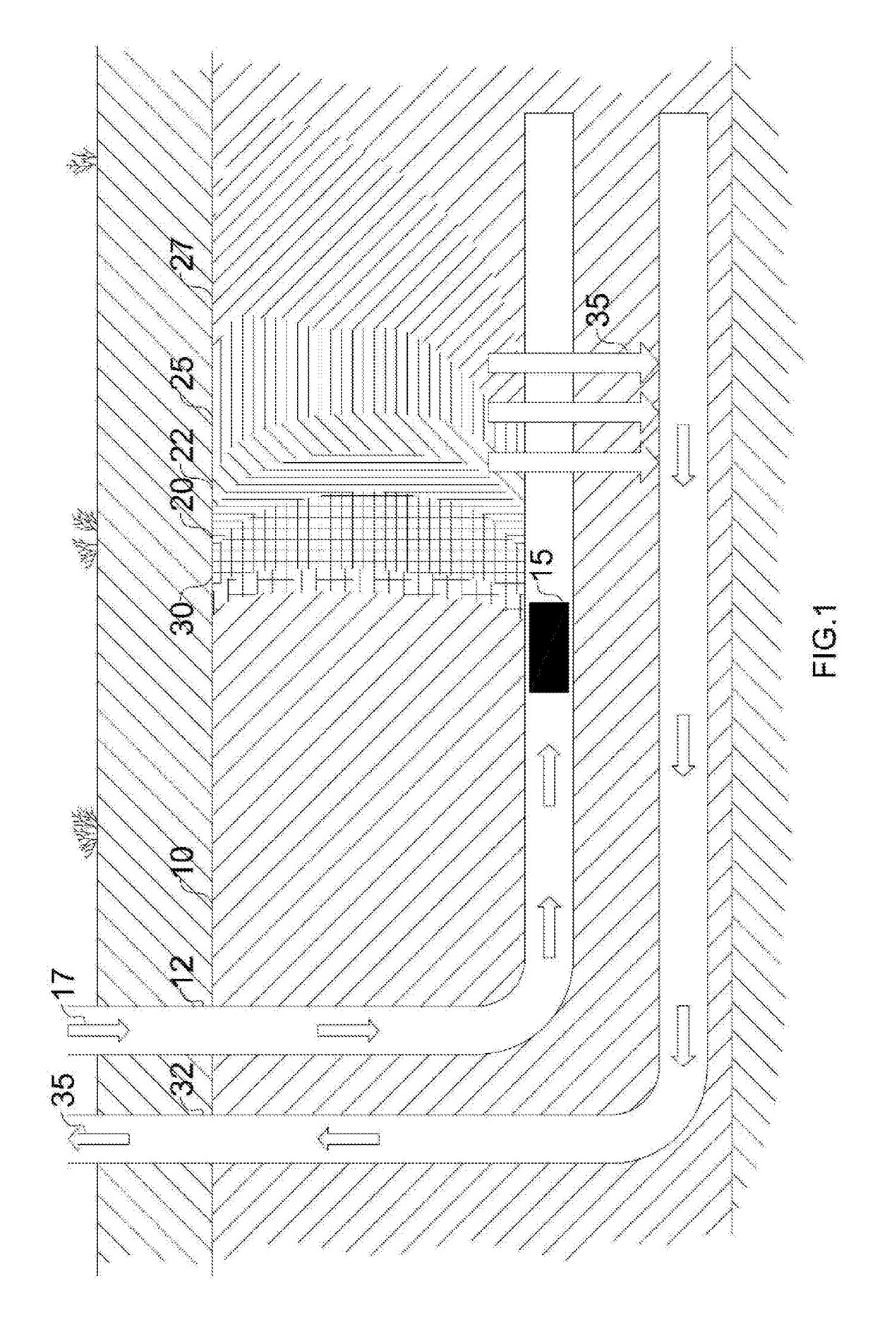
[0095]Reservoir modelling sensitivities for air injection in-situ combustion were carried out, according to the following procedure for steam linking and air injection for recovery of petroleum from a hydrocarbon-bearing subterranean formation, the formation being intersected by a completed well-pair including a generally horizontal injection well and a generally horizontal production well (see, FIGS. 1-5): 1) Start steam circulation (to surface) at the completed production well horizontal at a maximum steam injection flow rate of 4.56 m3 / h (Tubing T1)—steam temperature 320° C. 2) Continue with steam circulation at the completed production horizontal until the production well heel reaches 100° C.—at this temperature the heavy oil flows. 3) Switch from steam circulation to only steam injection with flow being resultant at a maximum well pressure limit of 4000 kPag. 4) Stop steam injection on the completed production well once 4,000 kPag is reached. Allow steam ...
PUM
 Abstract
Description
Claims
Application Information
 - R&D
- Intellectual Property
- Life Sciences
- Materials
- Tech Scout
- Unparalleled Data Quality
- Higher Quality Content
- 60% Fewer Hallucinations
Browse by: Latest US Patents, China's latest patents, Technical Efficacy Thesaurus, Application Domain, Technology Topic, Popular Technical Reports.
© 2025 PatSnap. All rights reserved.Legal|Privacy policy|Modern Slavery Act Transparency Statement|Sitemap|About US| Contact US: help@patsnap.com


