Semiconductor device

a technology of semiconductor devices and semiconductors, applied in semiconductor devices, semiconductor/solid-state device details, electrical apparatus, etc., to achieve the effect of improving electrical characteristics and reliability, and excellent thermal stability

Active Publication Date: 2018-05-10
SAMSUNG ELECTRONICS CO LTD
View PDF9 Cites 29 Cited by
  • Summary
  • Abstract
  • Description
  • Claims
  • Application Information

AI Technical Summary

Benefits of technology

[0005]Herein described exemplary embodiments are directed to a semiconductor device having improved electrical characteristics and reliability by providing a metal silicide layer having excellent thermal stability.

Problems solved by technology

In general, because a metal silicide layer used as a contact structure has poor thermal stability, a level of contact resistance may be greatly increased by the growth and / or agglomeration of grains that may occur in a subsequent process, such as annealing a gate dielectric layer.

Method used


Image

  • Semiconductor device
  • Semiconductor device
  • Semiconductor device

Examples


experiment 1-a

[0068]A nickel platinum (NiPt) layer was formed to have a thickness of 15 nm on a silicon (Si) layer, and was then subjected to a first annealing process at 250° C. for 20 seconds to form an amorphous silicide layer. After the first annealing process, a wet etching process was undertaken to remove a non-reactive metal layer that was not silicized, so that only the amorphous silicide layer remained on the silicon (Si) layer.

[0069]Subsequently, a second annealing process was performed using a rapid thermal processing (RTP) process, and annealing temperatures, for example, 420° C., 450° C., 500° C., 550° C., and 600° C., were varied for respective samples. Sheet resistances of silicide layers of the samples obtained as described above are shown as “A” in FIG. 3.

experiment 1-b

[0070]Similar to Experiment 1-A, a metal layer deposition process, a first annealing process, and a stripping process for forming an amorphous silicide layer were performed.

[0071]Subsequently, the second annealing process was performed using an MSA process including laser scanning, while the substrate was maintained at a temperature of 400° C., and annealing temperatures, for example, 900° C., 1050° C., 1150° C., 1250° C., and 1300° C., were varied for respective samples. Sheet resistances of silicide layers of samples obtained as described above are shown as “B” in FIG. 3.

[0072]As shown in the graph of FIG. 3, the metal silicide layer obtained under the annealing conditions (the second annealing process, i.e., the RTP process) according to Experiment 1-A may have a significantly increased level of sheet resistance at a temperature higher than 500° C. Conversely, the metal silicide layer obtained under the annealing conditions (the second annealing process, i.e., the MSA process) ac...


PUM


Abstract

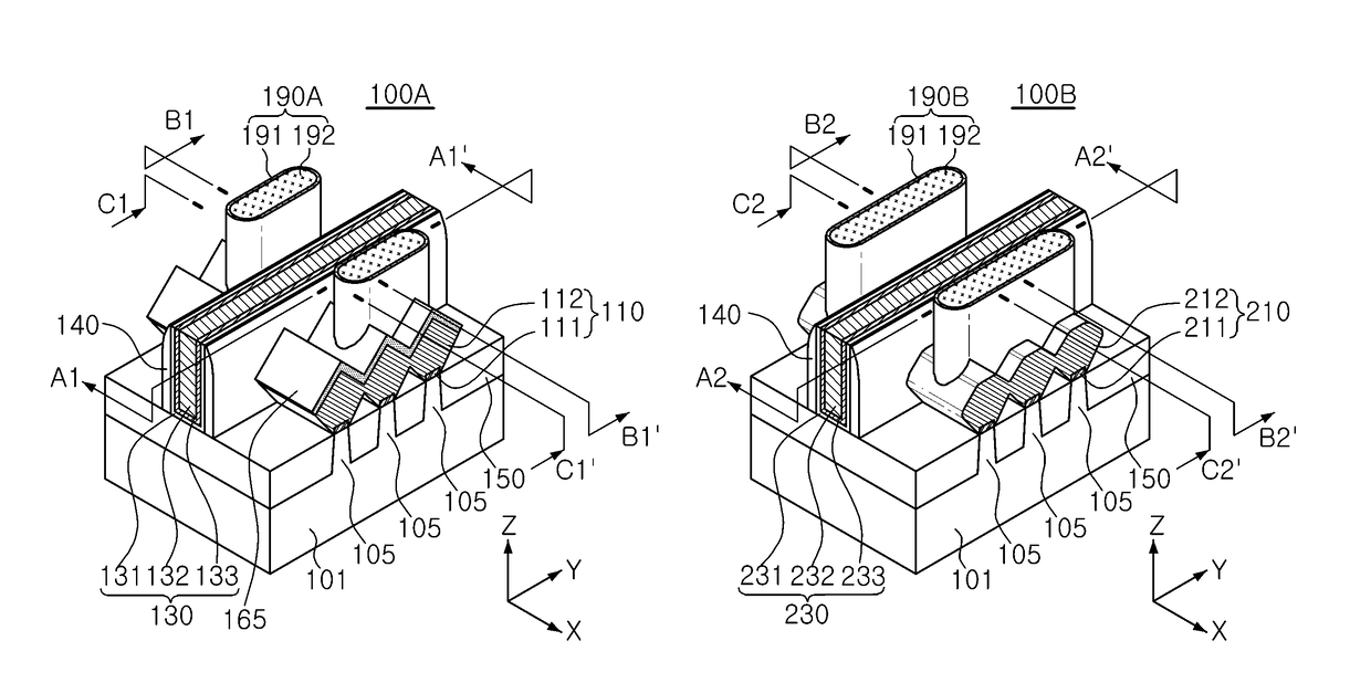
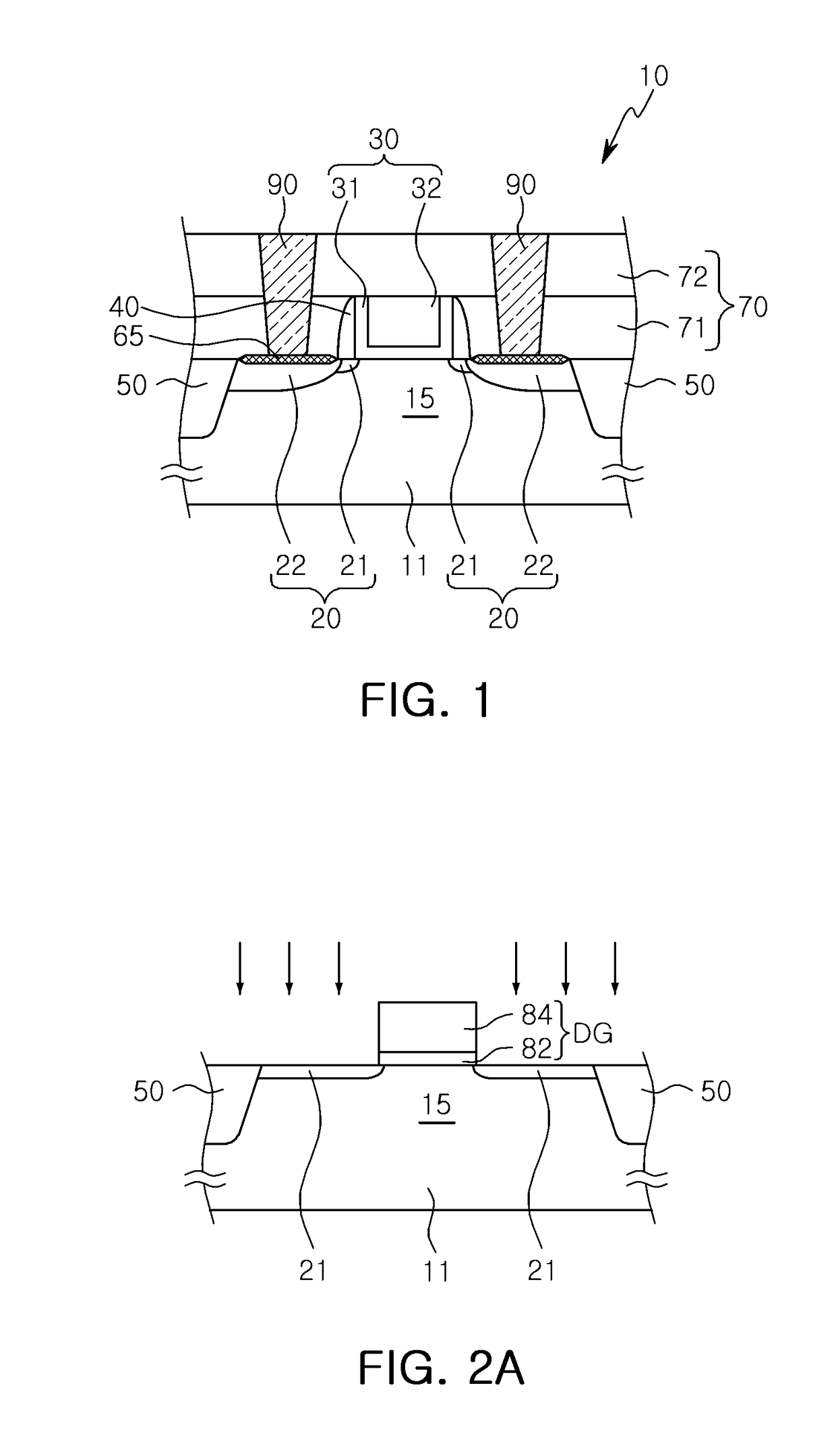
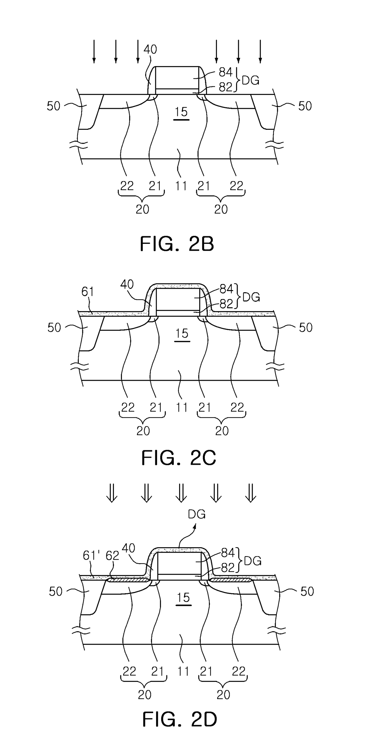
A semiconductor device includes: a substrate having an active region; a gate structure disposed in the active region; source/drain regions respectively formed within portions of the active region disposed on both sides of the gate structure; a metal silicide layer disposed on a surface of each of the source/drain regions; and contact plugs disposed on the source/drain regions and electrically connected to the source/drain regions through the metal silicide layer, respectively. The metal silicide layer is formed so as to have a monocrystalline structure.

Description

CROSS-REFERENCE TO RELATED APPLICATION[0001]This application claims benefit of priority under 35 USC § 119 to Korean Patent Application No. 10-2016-0148684, filed on Nov. 9, 2016 in the Korean Intellectual Property Office, the disclosure of which is incorporated herein by reference in its entirety.BACKGROUND1. Field[0002]The herein described exemplary embodiments relate to a semiconductor device.2. Description of Related Art[0003]As the demand for high performance, high speed, and multifunctionality in semiconductor devices has increased, the degree of integration of semiconductor devices has increased. When highly integrated, micropattern, semiconductor devices are manufactured, the micropatterns require a microwidth or a microdistance therebetween. To overcome the limitations of planar metal-oxide-semiconductor field-effect transistors (MOSFETs), semiconductor devices including fin field effect transistors (FinFETs), including a channel having a three-dimensional structure, have a...

Claims


Application Information

Patent Timeline
Patent Type & Authority Applications(United States)
IPC IPC(8): H01L29/417H01L27/092H01L29/51H01L29/423H01L21/02H01L21/3205
CPCH01L29/41725H01L27/0924H01L29/517H01L2924/0002H01L21/02425H01L21/32053H01L29/42356H01L29/456H01L29/785H01L21/823814H01L21/823821H01L21/28518H01L23/485H01L29/66545H01L29/7848H01L29/0847H01L29/165H01L29/41791H01L29/665H01L29/66795H01L21/32051H01L21/76897
Inventor KIM, JIN BUMKIM, GYEOMKIM, SEOK HOONPARK, TAE JINYOO, JEONG HOLEE, CHO EUNLEE, HYUN JUNGKIM, SUN JUNGSHIN, DONG SUK
Owner SAMSUNG ELECTRONICS CO LTD
Why Eureka
Try Eureka