
Multilayer transmission line plate

Active Publication Date: 2018-05-17
RESONAC CORP
View PDF2 Cites 3 Cited by
  • Summary
  • Abstract
  • Description
  • Claims
  • Application Information

AI Technical Summary

Benefits of technology

The present invention provides a simple and efficient way to reduce skew in differential transmission without complicating the manufacturing process. This invention improves the handling properties of the transmission line plate.

Problems solved by technology

Although the differential transmission system is advantageous for noise reduction, as the signal becomes faster, signal degradation to be caused due to generation of a common-mode noise has become problematic.
However, since the signal speed is different in the respective places, a deviation (skew) in arrival time of signal is generated at the receiving side, resulting in lowering of signal quality.
However, according to this method, imposition of the wiring pattern becomes inefficient, resulting in a material loss.

Method used


Image

  • Multilayer transmission line plate
  • Multilayer transmission line plate
  • Multilayer transmission line plate

Examples


first embodiment

Multilayered Transmission Line Plate

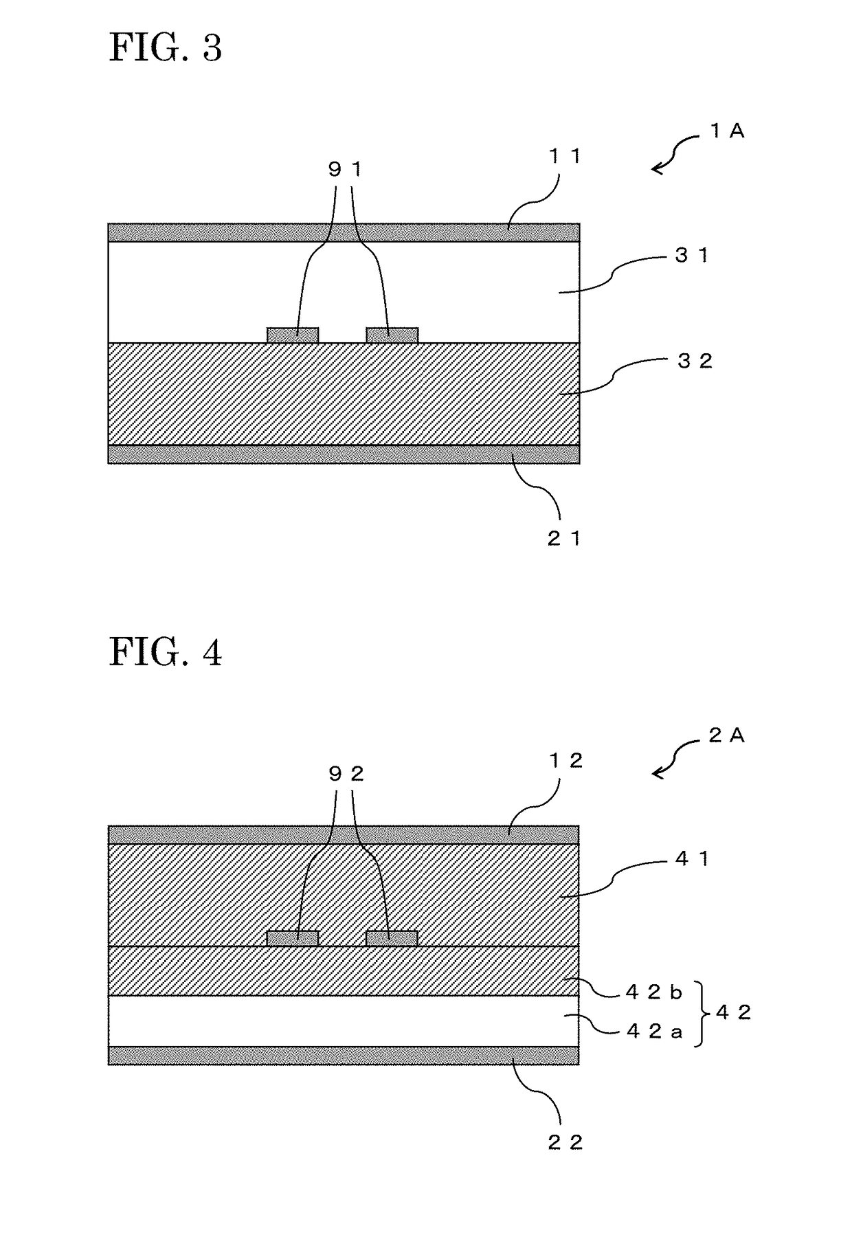
[0137]FIG. 3 is a schematic cross-sectional view showing a multilayered transmission line plate 1A according to the first embodiment of the present invention.

[0138]As shown in FIG. 3, the multilayered transmission line plate 1A according to the first embodiment of the present invention is a multilayered transmission line plate which includes a pair of ground layers 11 and 21; a differential wiring 91 disposed between the one-sided ground layer 11 of the pair of the ground layers 11 and 21 and the other ground layer 21; an insulating layer (1-I) 31 disposed between the differential wiring 91 and the one-sided ground layer 11; and an insulating layer (1-II) 32 disposed between the differential wiring 91 and the other ground layer 21, and in which the insulating layer (1-I) 31 is a layer containing a resin and not containing a glass cloth; the insulating layer (1-II) 32 is a layer containing a glass cloth and a resin; and the thickness of the insulat...

third embodiment

Multilayered Transmission Line Plate

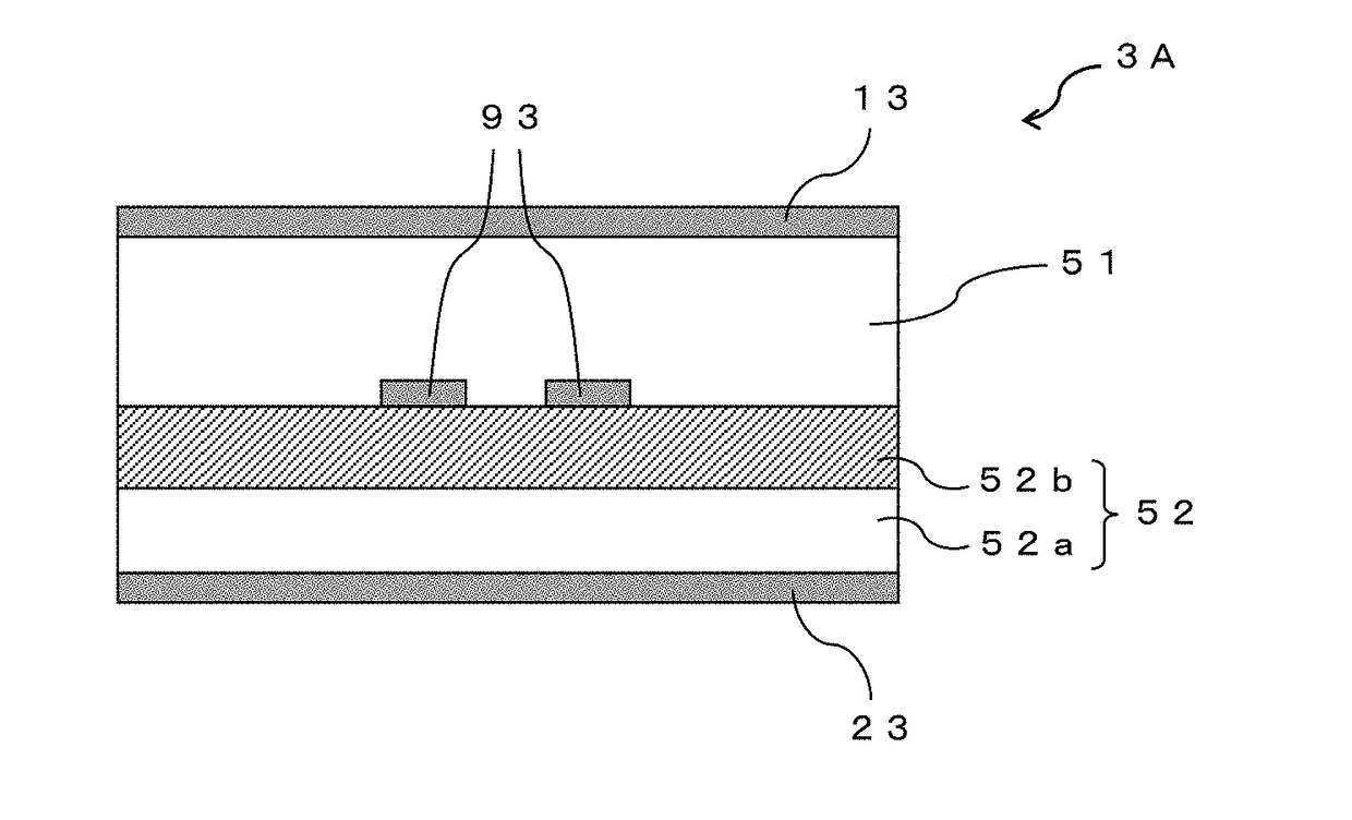
[0165]FIG. 5 is a schematic cross-sectional view showing a multilayered transmission line plate 3A according to the third embodiment of the present invention.

[0166]As shown in FIG. 5, the multilayered transmission line plate 3A according to the third embodiment of the present invention is a multilayered transmission line plate which includes a pair of ground layers 13 and 23; a differential wiring 93 disposed between the one-sided ground layer 13 of the pair of the ground layers 13 and 23 and the other ground layer 23; an insulating layer (3-I) 51 disposed between the differential wiring 93 and the one-sided ground layer 13; and an insulating layer (3-II) 52 disposed between the differential wiring 93 and the other ground layer 23, and in which the insulating layer (3-II) 52 has an insulating layer (3-IIA) 52a and an insulating layer (3-IIB) 52b laminated on the insulating layer (3-IIA) 52a; the insulating layer (3-I) 51 is a layer containing a re...

synthesis example 1

Production of Polyphenylene Ether Derivative (A)

[0181]A polyphenylene ether derivative (A) having at least one N-substituted maleimide group in a molecule thereof was produced according to the following procedures.

[0182]In a glass-made flask having a capacity of 2 liters and equipped with a thermometer, a reflux condenser, and a stirring device, which is capable of being heated and cooled, 190 parts by mass of toluene, 100 parts by mass of PP0640 (polyphenylene ether, number average molecular weight: about 16,000, manufactured by SABIC Innovative Plastics), and 1.35 parts by mass of p-aminophenol were charged and dissolved with stirring while setting a temperature within the flask at 90° C. and keeping the temperature. After confirming the dissolution through visual inspection, 2 parts by mass of PERBUTYL-I (t-butyl peroxy isopropyl monocarbonate, manufactured by NOF Corporation) and 0.15 parts by mass of manganese naphthenate were added, and the contents were allowed to react with ...


PUM

PropertyMeasurementUnit
Dielectric constantaaaaaaaaaa

Abstract

Provided is a multilayered transmission line plate including a pair of ground layers, a differential wiring disposed between a one-sided ground layer of the pair of ground layers and the other ground layer, an insulating layer (X) disposed between the differential wiring and the one-sided ground layer, and an insulating layer (Y) disposed between the differential wiring and the other ground layer, wherein the insulating layer (X) has a layer containing a resin and not containing a glass cloth; the insulating layer (X) or the insulating layer (Y) has a layer containing a glass cloth and a resin; and the thickness of the insulating layer (X) is equal to or less than the thickness of the insulating layer (Y).

Description

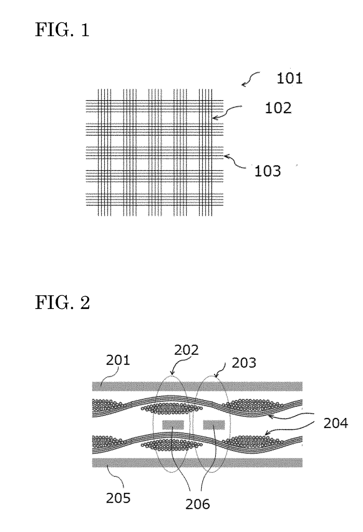
TECHNICAL FIELD[0001]The present invention relates to a multilayered transmission line plate, and in more detail, the present invention relates to a multilayered transmission line plate to be used for high-speed digital transmission by a Gbps-order differential transmission system.BACKGROUND ART[0002]Following an increase in speed of signal, the differential transmission system is widely adopted. Although the differential transmission system is advantageous for noise reduction, as the signal becomes faster, signal degradation to be caused due to generation of a common-mode noise has become problematic.[0003]Now, in an insulating layer of the multilayered transmission line plate, in order to secure handling properties of materials at the time of manufacture of multilayered transmission line plate, mechanical properties of the multilayered transmission line plate itself, and so on, a composite material of a glass cloth and a resin is widely used.[0004]As shown in FIG. 1, the glass clo...

Claims


Application Information

Patent Timeline
IPC IPC(8): H05K1/02H05K1/03H01P3/08B32B17/10H01P11/00H05K3/18
CPCH05K1/024B32B17/10H01P3/08H05K1/0245H05K1/0373B32B2307/206B32B2457/04H05K3/18H01P11/003H05K1/0366B32B17/04H05K1/0248H05K1/0298H05K1/036H05K2201/0195H01P3/026H05K1/0306H05K3/4626
Inventor KONDOU, YUUSUKEMIZUSHIMA, ETSUOTANIGAWA, TAKAONAGAI, YUKIFUKUDA, TOMIOIRINO, TESUROU
Owner RESONAC CORP
Learn More