
Condenser-evaporator tube

a technology of condenser and evaporator, which is applied in the field of tubes, can solve the problems of limiting the total energy that may be managed by each distillation device, the surface of the exchange tube, etc., and achieves the effect of high caloric energy transmission capacity

Active Publication Date: 2018-05-24
WGA WATER GLOBAL ACCESS SL
View PDF3 Cites 3 Cited by
  • Summary
  • Abstract
  • Description
  • Claims
  • Application Information

AI Technical Summary

Benefits of technology

The patent describes a new system for cooling electronic equipment using water. The system includes a special tube with thin walls that allows for a shorter distance between the inside of the tube and the outside of the equipment, which reduces the temperature. The system also includes a water-feeding channel and a water removal channel that are connected using support structures, which helps to transfer the water efficiently through the system. This new technology can help to improve the cooling performance of electronic equipment.

Problems solved by technology

The technical problem to solve is that the tubes that act as condenser on their inside face and as evaporators on their outside face, such as the horizontal tubes of a shell and tubes heat exchanger, reach low heat transfer coefficients per square meter of tube surface and Celsius degree of temperature differential between the vapor that flows inside the tube and the liquid fluid evaporating on the outside surface of the tube.
This limitation of the transmitted energy through the walls of current evaporator-condenser tubes restricts the number of condensation-evaporation cycles that may be realized with a source of energy at a given temperature, for example the steam from a cogeneration plant and a heat sink of lower temperature such as seawater, requires greater surfaces of exchange tubes inside the distillation devices and limits the total energy that may be managed by each distillation device.

Method used


Image

  • Condenser-evaporator tube
  • Condenser-evaporator tube
  • Condenser-evaporator tube

Examples


Embodiment Construction

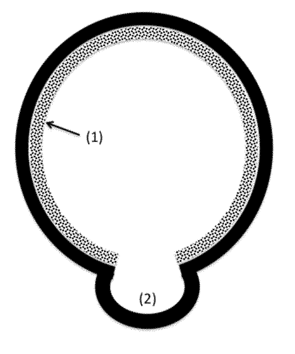
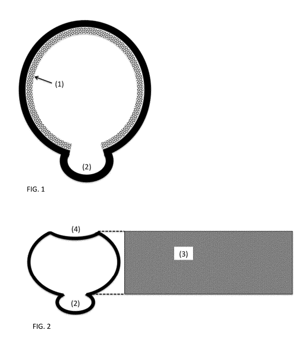
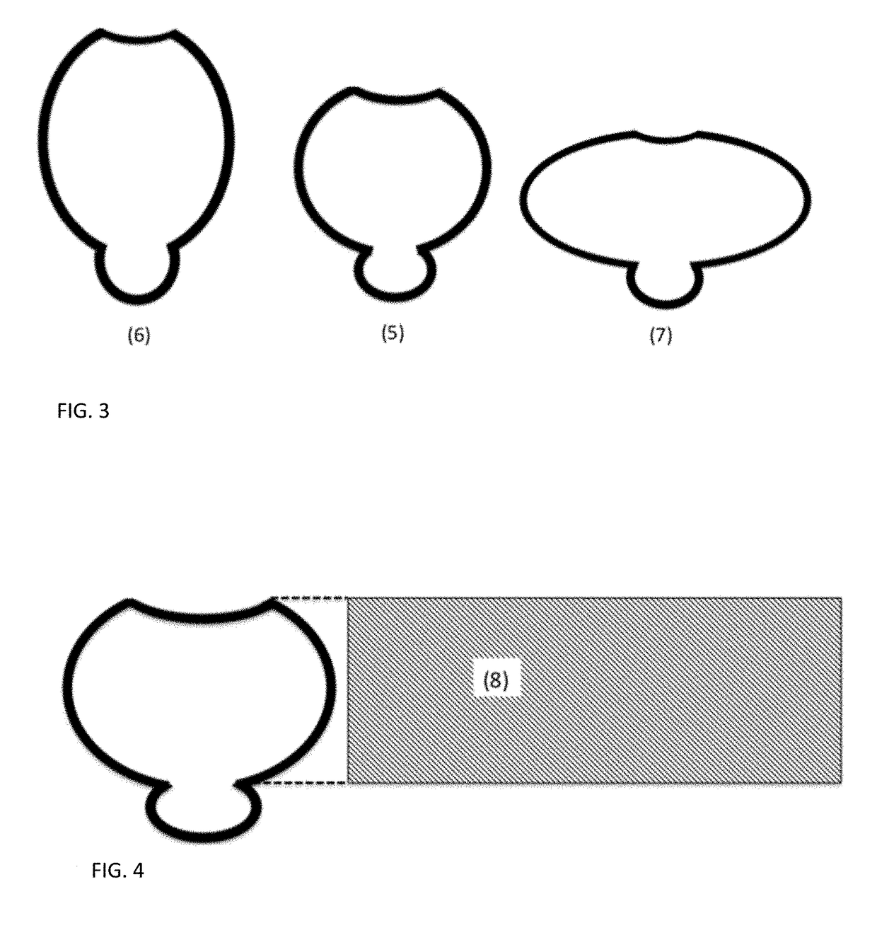
[0033]FIGS. 1 to 4 show a condenser-evaporator tube for evaporating and condensing water solutions or other liquids where the contact angle of the meniscus is smaller than 90°, that works as condenser on its inside face and as evaporator on its outside face; where the inside face is covered with a capillary structure in whose capillary spaces liquid fluid menisci are formed with a curved liquid-vapor interface and where the vapor of the fluid can condense at a pressure lower than vapor pressure and the condensed liquid is discharged through the evacuation channel 2; and where the outside face is covered with a capillary structure where the liquid to be evaporated forms menisci with a curved liquid-vapor interface and the evaporation occurs at the upper end 25, see FIG. 14, of the liquid menisci, where the thinnest liquid layer and the most efficient evaporation occurs.

[0034]According to FIG. 11, the tube may have an internal plate 14 and an external plate 23 for structural support s...


PUM

PropertyMeasurementUnit
Lengthaaaaaaaaaa
Depthaaaaaaaaaa
Contact angleaaaaaaaaaa

Abstract

Condenser-evaporator tube, in whose interior flows a vapor to be condensed and over which flows a liquid to be evaporated, where both inside and outside faces of this tube are covered with capillary structures configured for the formation of liquid menisci having a contact angle smaller than 90° where the liquid-vapor interface curves, which allows capillary condensation inside the tube and evaporation on the outside face at the upper end (25) of the liquid menisci where the liquid layer is thinnest and the evaporation most efficient.

Description

FIELD OF THE DISCLOSURE[0001]This invention relates to a tube that acts as condenser on its inside face and as evaporator on its outside face, with a high capacity of thermal energy transfer per surface unit and Celsius degree of temperature difference between said faces, usable in shell and tubes devices or other distillation devices.Background of the Invention[0002]The technical problem to solve is that the tubes that act as condenser on their inside face and as evaporators on their outside face, such as the horizontal tubes of a shell and tubes heat exchanger, reach low heat transfer coefficients per square meter of tube surface and Celsius degree of temperature differential between the vapor that flows inside the tube and the liquid fluid evaporating on the outside surface of the tube.[0003]In the specific case of shell and tubes exchangers for water desalination as used in MultiEffect Distillators MED, the thermal transfer coefficient of the horizontal tubes of these devices is...

Claims


Application Information

Patent Timeline
IPC IPC(8): F28D3/02F25B39/02F25B39/04
CPCF28D3/02F25B39/022F25B39/04B01D47/05B01D1/04B01D1/22F28F1/422F28F13/10F28F13/187F28F19/00F28B1/02F28G7/00F28D5/02F28F1/06F28D2021/0066B01D5/0009Y02A20/124
Inventor HANGANU, DAN ALEXANDRUNOMEN CALVET, JUAN EUSEBIO
Owner WGA WATER GLOBAL ACCESS SL
Learn More