Vehicle and noncontact power transmission and reception system

a power transmission and non-contact technology, applied in the direction of charging stations, electric propulsion mountings, transportation and packaging, etc., can solve the problem that the magnetic flux cannot reach the power receiving coil, and achieve the effect of reducing the variation of the coupling coefficient, reducing the coupling coefficient, and reducing the charg

Active Publication Date: 2018-06-21
TOYOTA JIDOSHA KK
View PDF0 Cites 4 Cited by
  • Summary
  • Abstract
  • Description
  • Claims
  • Application Information

AI Technical Summary

Benefits of technology

[0018]In the noncontact power transmission and reception system, when a state where a predetermined reference position provided in the vehicle body accords with the winding axis of the power transmission coil is assumed an aligned state, the winding axis of the power receiving coil is placed at a position deviating toward the one side in the reference direction from the reference position of the vehicle body. Accordingly, even if noncontact power transmission and reception is performed in the aligned state, or even if noncontact power transmission and reception is performed in a state where the power receiving coil deviates from the power transmission coil in the reference direction, an influence of the first region, positioned on the one side in the reference direction relative to the winding axis of the power receiving coil, with respect to the noncontact power transmission and reception hardly changes, and an influence of the space and/or the second region...

Problems solved by technology

In the meantime, in a case where aluminum or a metal member having a lower magnetic permeability and a lower electric resistance than aluminum is provided near the ...

Method used


Image

  • Vehicle and noncontact power transmission and reception system
  • Vehicle and noncontact power transmission and reception system
  • Vehicle and noncontact power transmission and reception system

Examples


embodiment 1

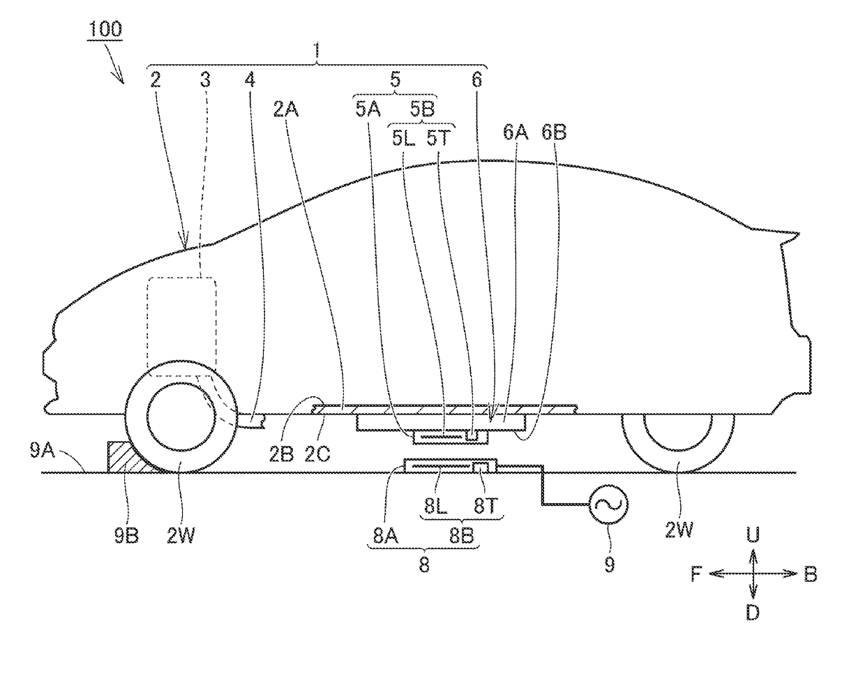
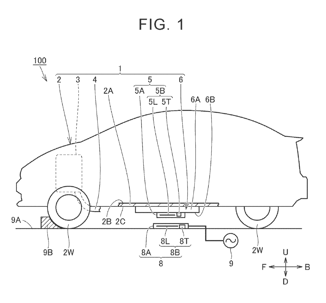
[0056]Referring now to FIGS. 1 to 7, the following describes a vehicle 1 and a noncontact power transmission and reception system 100 in Embodiment 1. FIG. 1 is a view schematically illustrating the vehicle 1 and the noncontact power transmission and reception system 100. FIG. 2 is a circuit diagram schematically illustrating the vehicle 1 and the noncontact power transmission and reception system 100.

[0057]In FIG. 1, an arrow U indicates an upper direction in a gravitational direction, and an arrow D indicates a lower direction in the gravitational direction. Arrows F, B indicate a vehicle front-rear direction of the vehicle 1. Although not illustrated in FIG. 1, arrows L, R in FIG. 3 and the like indicate a vehicle width direction of the vehicle 1. The meanings of these arrows are common in all the drawings described below.

[0058]Noncontact Power Transmission and Reception System 100

Referring now to FIGS. 1 and 2, the noncontact power transmission and reception system 100 is provid...

embodiment 2

[0138]FIG. 13 is a sectional view illustrating a noncontact power transmission and reception system 100B and a vehicle 1B in Embodiment 2, and corresponds to FIG. 4 in Embodiment 1. Embodiments 1 and 2 are different from each other in the following points.

[0139]The vehicle 1 of Embodiment 1 includes the engine 3 and the muffler 4, and can function as a hybrid vehicle or a plug-in hybrid vehicle. The vehicle 1B of Embodiment 2 does not include an engine and a muffler, and can function as an electric vehicle. In the vehicle 1B, a projection portion 2T is provided on a bottom surface 2C side of a vehicle body 2 (a floor panel 2A) so that the projection portion 2T is adjacent to a power reception apparatus 5 in the vehicle width direction.

[0140]The projection portion 2T is constituted by a metal member mainly containing at least one of iron and stainless, for example. The projection portion 2T of the present embodiment is constituted by a member provided integrally with the floor panel ...

embodiment 3

[0142]FIG. 14 is a sectional view illustrating a noncontact power transmission and reception system 100C and a vehicle 1C in Embodiment 3, and corresponds to FIG. 4 in Embodiment 1. Embodiments 1 and 3 are different from each other in the following points.

[0143]In the vehicle 1 of Embodiment 1, the power reception apparatus 5 is fixed to the bottom surface 2C side of the vehicle body 2 (the floor panel 2A) via the power storage apparatus 6. In the vehicle 1C of Embodiment 3, a power reception apparatus 5 is fixed to a bottom surface 2C side of a vehicle body 2 (a floor panel 2A) via a metal plate 6S. A power storage apparatus 6 may be placed on the bottom surface 2C side of the vehicle body 2 (the floor panel 2A) or may be provided inside the vehicle body 2 (on a top side of the floor panel 2A), as needed.

[0144]The metal plate 6S is constituted by a member made of aluminum, for example. A bottom surface 6T of the metal plate 6S functions similarly to the bottom surface 6B of the pow...


PUM


Abstract

A vehicle capable of receiving an electric power in a contactless manner includes a vehicle body and a power reception apparatus. A first region made of aluminum or formed so that a magnetic permeability and an electric resistance thereof are lower than a magnetic permeability and an electric resistance of aluminum, respectively, is provided at a position on one side in a reference direction relative to the power reception apparatus. A space and/or a second region formed so that a magnetic permeability and an electric resistance thereof are higher than the magnetic permeability and the electric resistance of the first region, respectively, is provided at a position on the other side in the reference direction. A winding axis of a power receiving coil is placed at a position deviating toward the one side in the reference direction from a central position in a vehicle width direction.

Description

CROSS-REFERENCE TO RELATED APPLICATIONS[0001]This application claims priority to Japanese Patent Application No. 2016-247827 filed on Dec. 21, 2016, which is incorporated herein by reference in its entirety including the specification, drawings and abstract.BACKGROUND1. Technical Field[0002]This disclosure relates to a vehicle capable of receiving an electric power in a contactless manner from a power transmission apparatus provided outside a vehicle body, and a noncontact power transmission and reception system.2. Description of Related Art[0003]As described in Japanese Patent Application Publication No. 2012-188116 (JP 2012-188116 A), Japanese Patent Application Publication No. 2013-154815 (JP 2013-154815 A), Japanese Patent Application Publication No. 2013-146154 (JP 2013-146154 A), Japanese Patent Application Publication No. 2013-146148 (JP 2013-146148 A), Japanese Patent Application Publication No. 2013-110822 (JP 2013-110822 A), Japanese Patent Application Publication No. 2013...

Claims


Application Information

Patent Timeline
IPC IPC(8): B60L11/18H02J7/02
CPCB60L11/1811B60L11/1829B60L11/182H02J7/025B60K2001/0438H02J50/12B60L53/12B60L53/38H02J7/0042B60K1/04Y02T90/12Y02T10/7072Y02T90/14B60L53/20B60L53/122H02J2310/48Y02T10/70
Inventor YUASA, HIROAKI
Owner TOYOTA JIDOSHA KK
Why Eureka
Try Eureka