Micropump-fed autogenous pressurization system

a technology of autogenous pressurization and micropump, which is applied in the direction of cosmonautic vehicles, rocket engine plants, machines/engines, etc., can solve the problems of large volume, heavy tanks, and inability to control the pressure profile of tanks, and achieves high efficiency, high cost, and high cos

Inactive Publication Date: 2018-06-21
FLIGHT WORKS INC
View PDF4 Cites 11 Cited by
  • Summary
  • Abstract
  • Description
  • Claims
  • Application Information

AI Technical Summary

Benefits of technology

[0008]It is another object of the invention to provide such an autogenous system through which the tank pressure profile, and therefore thrust, and can be controlled.

Problems solved by technology

This approach leads to large, heavy tanks since they have to be designed for the initial pressure.
Also, this approach does not allow for control of the tank pressure profile, and therefore thrust.
As a result, these systems are heavy, complex, expensive, and prone to component failures.
These high pressure systems are expensive, heavy, and add complexity and risks of leakage, particularly over long missions.
This type of system presents many drawbacks which make it impractical for the desired applications.
These drawbacks include suboptimal propellant packaging (due to the elevated temperature and therefore reduced liquid density leading to larger tanks), challenging propellant thermal control (in order to keep the system at the desired operating pressure), and two-phase flows in the feed system and injector leading to combustion instabilities.
These separate components add weight and complexity, and can cause reliability challenges.

Method used


Image

  • Micropump-fed autogenous pressurization system
  • Micropump-fed autogenous pressurization system
  • Micropump-fed autogenous pressurization system

Examples


Embodiment Construction

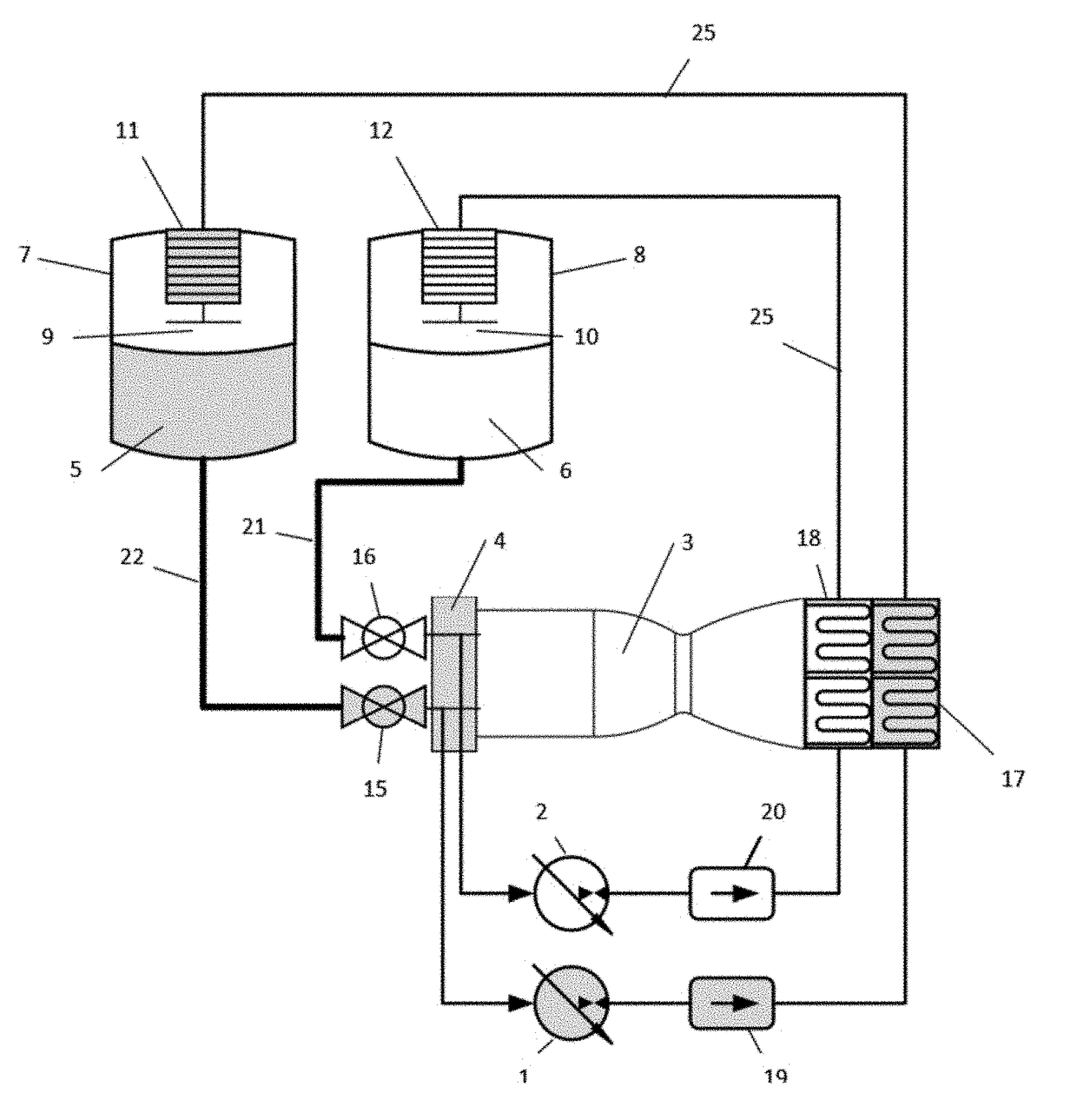
[0030]The autogenous system for controlling pressurization of a propellant tank in a pressure-fed propulsion system may be either a monopropellant system, using a single propellant, or a bipropellant system, using at least two separate propellants such as a fuel and an oxidizer. As used herein, the term “autogenous” refers to a system that can function in an essentially closed loop with minimal assistance from external components. In a bipropellant system herein, the two propellants are maintained in primarily separate loops, but for their combined use in a combustion chamber, as described in further detail below.

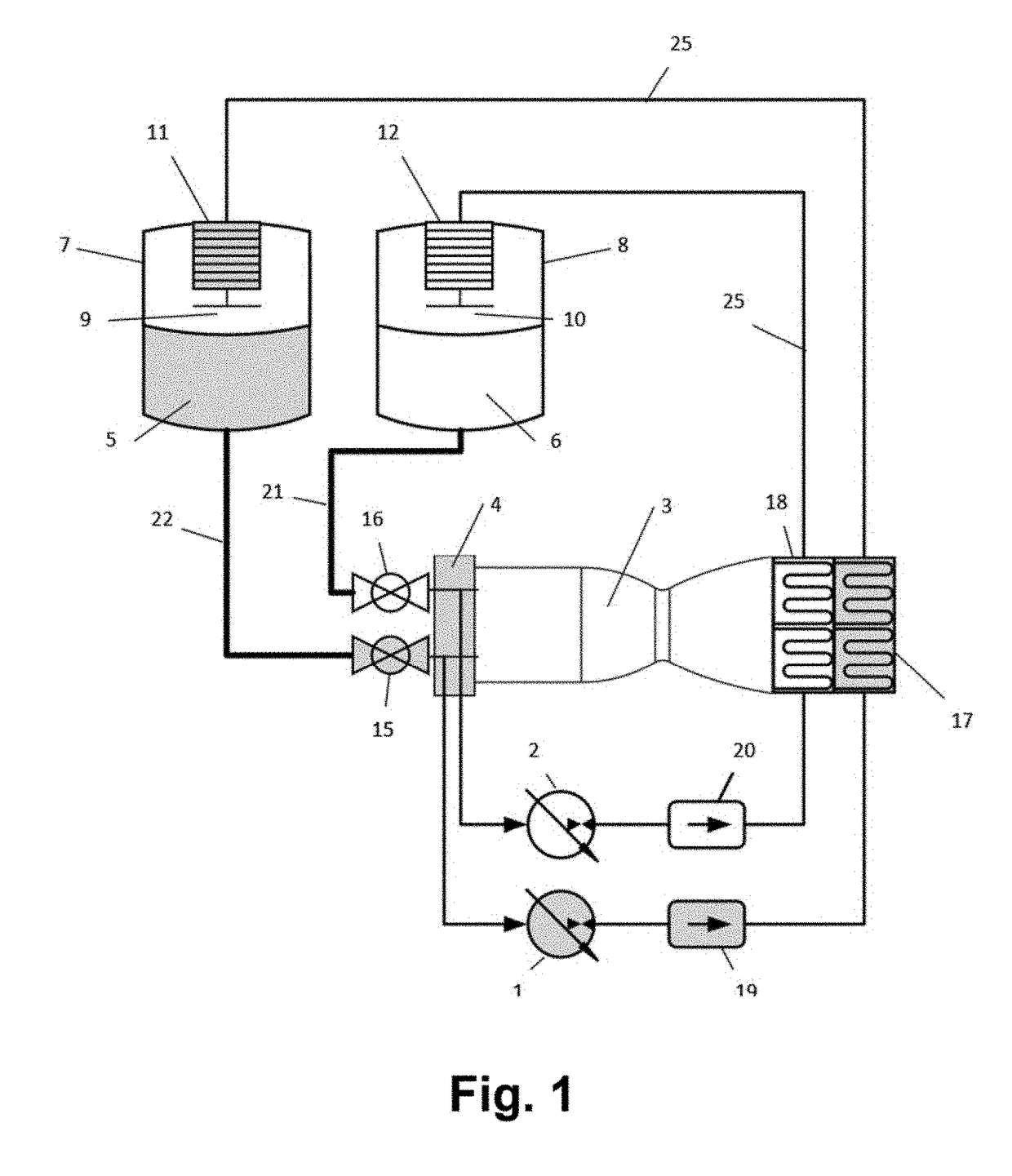
[0031]FIG. 1 shows a bipropellant pump-fed autogenous system including a micropump 2 that pumps a propellant or fuel 6 from a propellant tank or fuel tank 8 into a combustion chamber 3 of an engine, such as a rocket engine, in which the propellant or fuel 6 is evaporated and heated. The micropump 2 controls the pressurization rate by controlling the flow of the fuel 6.

[0032...


PUM


Abstract

An autogenous system for controlling pressurization of a propellant tank in a pressure-fed propulsion system. The system includes at least one micropump that pumps a high vapor pressure liquid propellant or a propellant with low temperature critical point from the propellant tank into an engine in which a small portion of the propellant is evaporated and heated. The micropump controls a pressurization rate of a flow of the propellant. A method of controlling pressurization of a propellant tank in such a system includes pressurizing a propellant tank containing a high vapor pressure liquid propellant or a propellant with low temperature critical point; controlling a flow of a small amount of the propellant from the propellant tank to a combustion chamber using at least one micropump; heating and vaporizing the propellant in a heat exchanger; and using the micropump to control the amount of propellant vaporized and heated, thereby controlling the pressurization rate.

Description

BACKGROUND OF THE INVENTION[0001]The invention relates to a system, method, and apparatus for controlling pressurization of pressure-fed rocket and spacecraft propellant tanks.[0002]The simplest approach for pressurizing the propellant tanks in a pressure-fed propulsion system is based on having a large amount of ullage. In this approach, the tanks are initially partially filled with propellant, typically 40 to 60%, with the balance consisting of a pressurization gas, such as helium or nitrogen. This large initial pressurant volume fraction is dictated by the need to have adequate feed pressure as the propellants are depleted. For example, under isothermal conditions, with an initial propellant load of 50%, the final pressure in the tank is half of the initial pressure. This approach leads to large, heavy tanks since they have to be designed for the initial pressure. Also, this approach does not allow for control of the tank pressure profile, and therefore thrust.[0003]To circumvent...

Claims


Application Information

Patent Timeline
Patent Type & Authority Applications(United States)
IPC IPC(8): F02K9/46F02K9/60F02K9/56F02K9/58F02K9/62F02K9/97B64G1/40
CPCF02K9/46F02K9/605F02K9/563B64G1/401F02K9/62F02K9/97B64G1/402F02K9/58F02K9/50
Inventor BESNARD, ERIC G.
Owner FLIGHT WORKS INC
Why Eureka
Try Eureka