Porous structure for bone implants
- Summary
- Abstract
- Description
- Claims
- Application Information
AI Technical Summary
Benefits of technology
Problems solved by technology
Method used
Image
Examples
first embodiment
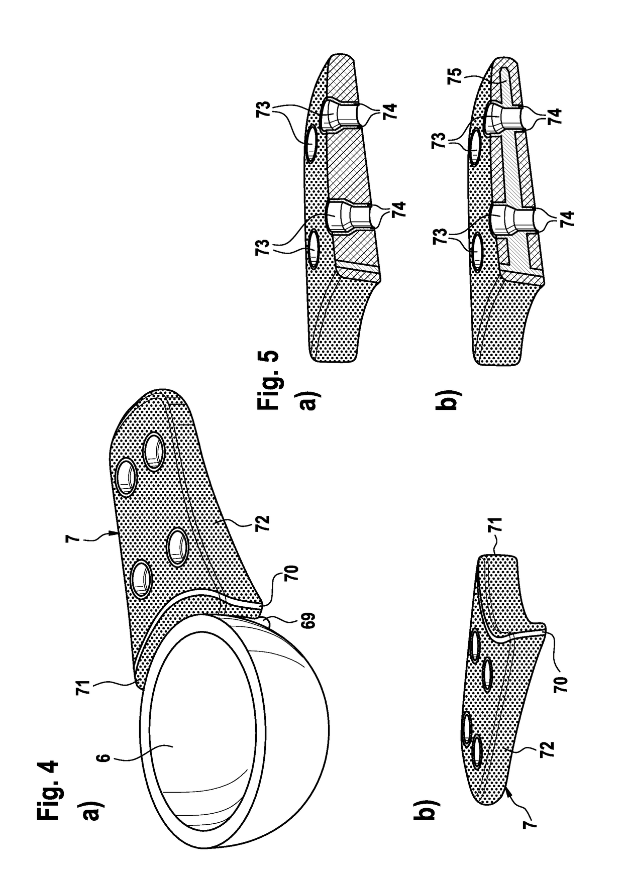
[0064]a bone implant used for an endoprosthesis is shown in FIG. 4a, b. It comprises an acetabular cup 6 for the acetabular portion of hip endoprosthesis. The acetabular cup 6 is made of solid biocompatible material as known in the art. However, due to defects in the natural bone where the acetabular cup 6 is to be implanted, it may be necessary to provide a bone implant 7 for augmentation. The bone implant 7 is a plate shaped augment and it features a solid inner wall 70 and a first porous structure 71 on its inner and a second porous structure 72 on its outer side, the porous structure 71, 72 being configured as described above. The solid inner wall acts as a bulkhead isolating the porous structures 71, 72 from each other. Thereby, the porous structures 71, 72 can serve different purposes. The porous structure 71 may serve as a contacting surface to the acetabular cup 6. For affixing to the acetabular cup 6 cement 69 may be used, wherein the cement 61 enters the interconnected por...
third embodiment
[0068]a bone implant is shown in FIGS. 9 and 10. It is configured as a tibial augment cone 8 to be used for the tibial component of a knee endoprosthesis (not shown). The tibial augment cone 8 is configured to be a substitute for defective bone material at the proximal end of the tibia, filling voids caused by bone defects. Thereby a full base is formed to which the tibial component of the knee endoprosthesis can be attached. To this end the tibial augment cone 8 is manufactured using the porous structure according to the invention. A first portion 81 of the porous structure is applied on inner surface of the tibial augment cone, in order to make contact by means of bone cement (not shown) with a shaft of the tibial component passing through the interior space of the tibial augment cone 8. By virtue of the high porosity a good penetration could be achieved, thereby providing for a robust fixation. A second portion 82 of the porous structure is applied to an outer surface of the tibi...
fourth embodiment
[0069]a bone implant is shown in FIG. 11. It is configured as a spinal cage 9 to be placed into an intervertebral space for promoting fusion of two adjacent vertebrae (not shown). It acts as a substitute for an intervertebral disc and prevents collapsing of the intervertebral space in case of removal of said disc. Usually two cages 9 are placed side by side in a single intervertebral space. An inner core 91 is formed by the porous structure (in FIG. 11a symbolized by cross-hatching), thereby promoting bone ingrowth for improved fusioning of the two adjacent vertebra. The core 91 is surrounded by an encasement 90 made of solid material acting as a reinforcing element for providing mechanical strength to the spinal cage 9. On a top and bottom surface of the encasement 90 a plurality of teeth 92 is provided. The teeth 92 are shaped like slanted pyramids for arresting the cage into its place, thereby preventing any unwanted dislocation. A variant of a cage 9′ is shown in FIG. 11b. It is...
PUM
| Property | Measurement | Unit |
|---|---|---|
| Thickness | aaaaa | aaaaa |
| Thickness | aaaaa | aaaaa |
| Thickness | aaaaa | aaaaa |
Abstract
Description
Claims
Application Information
 - R&D
- Intellectual Property
- Life Sciences
- Materials
- Tech Scout
- Unparalleled Data Quality
- Higher Quality Content
- 60% Fewer Hallucinations
Browse by: Latest US Patents, China's latest patents, Technical Efficacy Thesaurus, Application Domain, Technology Topic, Popular Technical Reports.
© 2025 PatSnap. All rights reserved.Legal|Privacy policy|Modern Slavery Act Transparency Statement|Sitemap|About US| Contact US: help@patsnap.com


