Shock absorber based on the cutting, inward-folding and crushing of composite tube

a composite tube and shock absorber technology, applied in the direction of shock absorbers, elastic dampers, bumpers, etc., can solve the problems of large scraps of carbon fiber tubes, large disturbances in the surrounding structure, and large influence on surrounding structures, so as to improve the interaction force, strengthen the rigidity of the tube, and simplify the overall structure

Active Publication Date: 2018-07-19
SHANGHAI JIAO TONG UNIV
View PDF9 Cites 2 Cited by
  • Summary
  • Abstract
  • Description
  • Claims
  • Application Information

AI Technical Summary

Benefits of technology

[0003]The purpose of the present invention is to provide an efficient shock absorber based on the cutting, inward-folding and crushing of composite tube to overcome the above mentioned defects in existing technologies, which has a simple overall structure and can play a structural support role at the same time. Based on a composite tube, the device absorbs impact energy through layering, bend

Problems solved by technology

However, during the implementation of this solution, the cut strips expand towards the outside of a cap, extend towards the four sides, and are wound around the cap, generating a relatively large disturban

Method used


Image

  • Shock absorber based on the cutting, inward-folding and crushing of composite tube
  • Shock absorber based on the cutting, inward-folding and crushing of composite tube
  • Shock absorber based on the cutting, inward-folding and crushing of composite tube

Examples


example 1

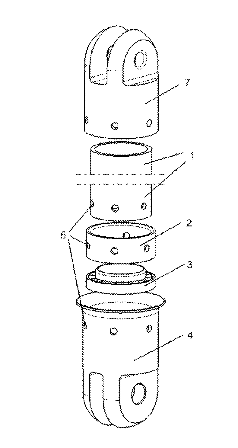
[0038]An shock absorber based on the cutting, inward-folding and crushing of composite tube, with a structure as shown in FIG. 1, including a composite tube 1, a destructing cap 4, a flat-pressing cap 7, a cutter 3 and a positioning tube 2. The cutter 3 is installed in the destructing cap, and has a lower end connected to an inner flange 9 of the destructing cap and an upper end connected to the positioning tube 2. The positioning tube 2 is positioned in the destructing cap, and has a lower surface in contact with the cutter 3. The destructing cap, the positioning tube 2 and the composite tube 1 are respectively provided with aligned pin holes 5, and bound together with a pin; and the other end of the composite tube is connected with the flat-pressing cap 7 through a pin.

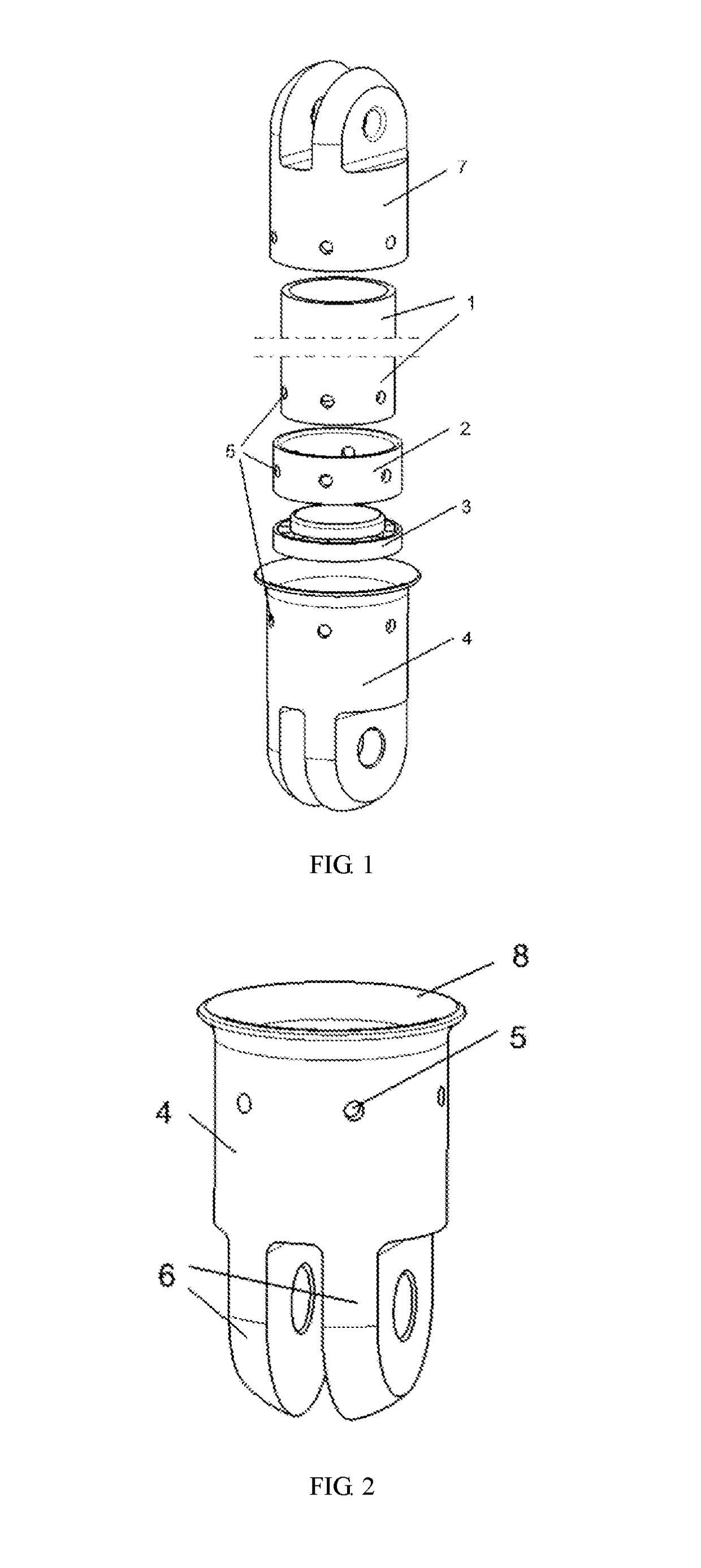
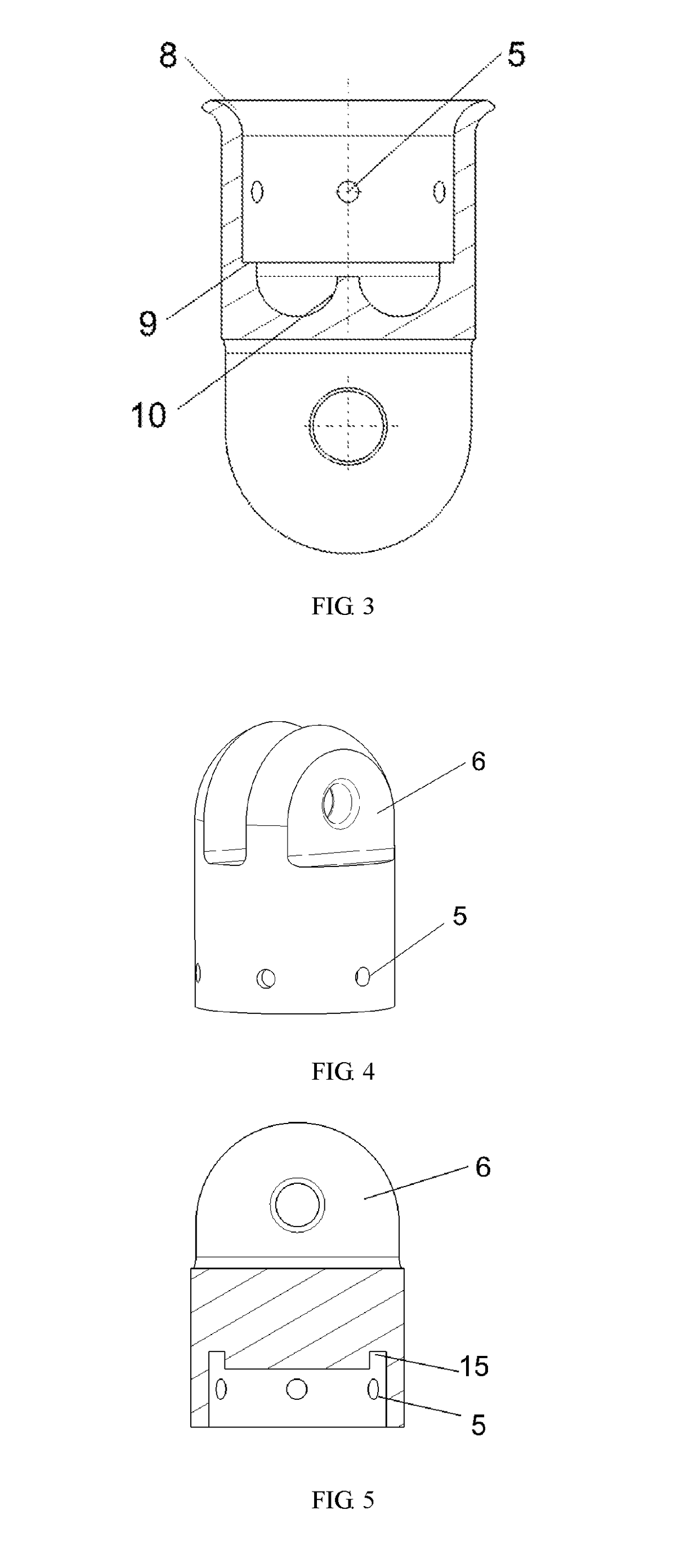
[0039]The destructing cap 4, with a structure as shown in FIG. 2-3, includes a lug 6, an inlet radius 8, a flange 9 and a guide curved face 10. The inlet radius 8 is positioned at the upper end of the destructing ca...

example 2

[0045]The destructing cap may be in another form. As shown in FIG. 10, the destructing cap is also capable of being provided with no cutter inside, and the inner diameter of the destructing cap is identical with the outer diameter of the composite tube such that the composite tube is in a direct contact with the inner wall of the destructing cap. For the energy absorbing device adopted in this example, the schematic view of the working process thereof can be seen in FIG. 11. The cutter is removed. The inner diameter of the destructing cap is reduced to be equal to the outer diameter of the composite tube, so that the composite tube directly contacts the inner wall of the destructing cap. When bearing an axial load, the composite tube starts to extrude the lower cap. First, the pin fails. Then, the composite tube continuously moves towards the axial direction until reaching the guide curved face 10 in the destructing cap, and changes direction during movement when guided by the guide...


PUM

PropertyMeasurementUnit
Forceaaaaaaaaaa
Diameteraaaaaaaaaa
Energyaaaaaaaaaa

Abstract

The present invention relates to an shock absorber based on the cutting, inward-folding and crushing of composite tube, comprising a destructing cap, a flat-pressing cap, a cutter and a positioning tube. The cutter is positioned in the destructing cap, and has a lower end connected to an inner flange of the destructing cap and an upper end connected to the positioning tube. The positioning tube is positioned in the destructing cap and closely connected to the inner wall of the destructing cap, and has a lower surface in contact with the cutter. The destructing cap, the positioning tube and the composite tube are respectively provided with aligned pin holes, and bound together with a pin. Energy is absorbed through destruction generated due to cutting and inward-folding of the composition tube. Energy can also be absorbed through destruction generated due to the inward-folding of the composite tube, without using the cutter. Compared to existing technology, the device may be used as a structural component in a normal working state. In the colliding and crushing state, the device fully destructs the composite. The present invention has the following advantages: the energy-absorption ratio is high; and the energy absorbing device only bears an axial force in the process that the composite is being destroyed, does not bend or rupture, keeps the structure stable, and avoids spattering of scraps.

Description

BACKGROUND OF THE INVENTIONTechnical Field[0001]The present invention relates to the technical field of energy absorption structures, and particularly to A shock absorber based on the cutting, inward-folding and crushing of composite tube.Description of the Related Art[0002]Lower crashworthy structures of modern commercial airplanes and the anti-collision beams of vehicles are commonly made of metal materials. The energy generated by impact destruction is usually absorbed through plastic deformations. Limited by the metal materials, the ratio of the absorbed energy to the structural weight is relatively low. A composite structure is light, so more energy can be absorbed. S. Heimbs proposed a solution in which the composite is cut into a plurality of slim strips using connectors such that the composite generates a relatively complicated destruction form to absorb energy. However, during the implementation of this solution, the cut strips expand towards the outside of a cap, extend to...

Claims


Application Information

Patent Timeline
IPC IPC(8): F16F7/00F16F7/12
CPCF16F7/003F16F7/127F16F7/123F16F2224/0241F16F2230/0052F16F2236/04B60R19/02B60R2019/026F16F7/124F16F7/126B61F19/04
Inventor YU, ZHEFENGFU, YI
Owner SHANGHAI JIAO TONG UNIV
Why Eureka
Try Eureka