LED flip chip plant grow light

a technology of flip-chip plants and light, which is applied in the direction of light sources, semiconductor devices for light sources, light and heating apparatus, etc., can solve the problems of high chip temperature, insufficient thermal conductivity, and high cost of ceramics, and achieves short life span, high cost, and strong thermal decay

Inactive Publication Date: 2018-07-26
STARLITE LED
View PDF2 Cites 28 Cited by
  • Summary
  • Abstract
  • Description
  • Claims
  • Application Information

AI Technical Summary

Benefits of technology

[0012]Various embodiments are directed to a LED flip chip chip-on-board (COB) module (or “LED COB module”) that is advantageous to conventional techniques employed for the plant lighting. The LED COB module is configured to overcome the obstacles that conventional plant grow lights are suffering from, such as (i) narrow emitting spectrum from LED Packages, (ii) strong thermal decay and short life span of red and deep-red LED packages, and (iii) high cost on red and deep-red LED packages.

Problems solved by technology

Plant grow lights are generally applied while naturally occurring light is insufficient, such as due to high latitude location or seasonal changes.
These applied material results in insufficient thermal dissipation and higher chip temperature.
However, ceramic is relatively expensive and not necessarily perform sufficient thermal conductivity.
Plant grow lights employing LED packages conventionally suffer from several other problems, such as insufficient spectrum coverage, shorter life span caused by weak thermal dissipation and high cost of the deep-red LED packages 102.
However, this method requires a larger module space and more LED Packages that result in higher manufacture cost, mostly because of the higher cost of the red LED packages and deep-red LED packages.
Furthermore, the red and deep-red LED packages are very sensitive to thermal conditions.

Method used


Image

  • LED flip chip plant grow light
  • LED flip chip plant grow light
  • LED flip chip plant grow light

Examples


Embodiment Construction

[0041]Various embodiments will now be described more fully with reference to the accompanying drawings, in which some, but not all embodiments of the disclosure are shown. This disclosure may be embodied in many different forms and should not be construed as limited to the embodiments set forth; rather, these example embodiments are provided so that this disclosure will be thorough and complete, and will fully convey the scope of the disclosure to those skilled in the art. Like numbers refer to like elements throughout.

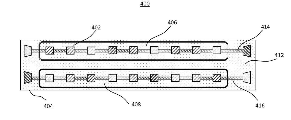
[0042]FIGS. 4(a) and 4(b) respectively show top-view and side-view structural diagrams of an LED COB module 400, in accordance with some embodiments. Instead of employing royal-blue and / or deep-red LED packages, the LED COB module 400 may include ultraviolet (UV) LED flip chips 402 bonded on a Metal Core Printed Circuit Board (MCPCB) 404, and two separate phosphor or fluorescent dye layers 406 and 408. The phosphor or fluorescent dye layer may be a direct coating of p...


PUM


Abstract

Techniques for providing plant growth lights with improved performance and cost are discussed herein. Some embodiments may provide for a light emitting diode (LED) flip chip chip-on-board (COB) module for optimizing plant growth, including: a circuit board; ultraviolet (UV) LED flip chips connected to the circuit board; a royal-blue phosphor or fluorescent layer covering a first portion of the UV LED flip chips; and a deep-red phosphor or fluorescent layer covering a second portion of the UV LED flip chips. The royal-blue phosphor or fluorescent layer absorbs UV light generated by the first portion of the UV LED flip chips and converts the UV light into broad-band light in royal-blue spectrums. The a deep-red phosphor or fluorescent layer absorbs UV light generated by the second portion of the UV LED flip chips and converts the UV light into broad-band light in deep-red spectrums.

Description

CROSS-REFERENCE TO RELATED APPLICATION[0001]The present application is a U.S. National Stage of International Application No. PCT / US2015 / 055570, filed Oct. 14, 2015, which is incorporated by reference in its entirety.TECHNICAL FIELD[0002]The example embodiments of the present invention generally relate to techniques for providing light emitting diode devices, and more particularly to designs and fabrication processes of chip on board light emitting diode devices for optimized plant growth.BACKGROUND[0003]Plant grow lights are designed to enhance or stimulate plant growth by photosynthesis through appropriate spectral radiation. Plant grow lights are generally applied while naturally occurring light is insufficient, such as due to high latitude location or seasonal changes. Today, plant grow lights also provide supplemental lighting for photosynthesis to accelerate plant growth or boost production of nutritious contents.[0004]Based on the results of photosynthesis research, an ideal ...

Claims


Application Information

Patent Timeline
Patent Type & Authority Applications(United States)
IPC IPC(8): A01G7/04H01L25/075H01L33/50H01L33/62H01L33/64F21K9/64F21V29/70F21V19/00
CPCA01G7/045H01L25/0753H01L33/502H01L33/62H01L33/647F21K9/64F21V29/70F21V19/0015F21Y2115/10H01L33/32H01L33/504H01L33/642H05K1/05H05K3/284H05K2201/09054H05K2201/10106H05B45/00H05B45/20Y02P60/14
Inventor CHEN, PAOHAN, SANG
Owner STARLITE LED
Why Eureka
Try Eureka