Flexible membrane

a flexible membrane and membrane technology, applied in the field of flexible membranes, can solve the problems of limiting the acoustic performance of known mems capacitive microphone devices, reducing the quality of detected sound, etc., and achieves the effects of strengthening the membrane, simplifying the formation process, and reducing the cost of the devi

Active Publication Date: 2018-07-26
CIRRUS LOGIC INC
View PDF0 Cites 7 Cited by
  • Summary
  • Abstract
  • Description
  • Claims
  • Application Information

AI Technical Summary

Benefits of technology

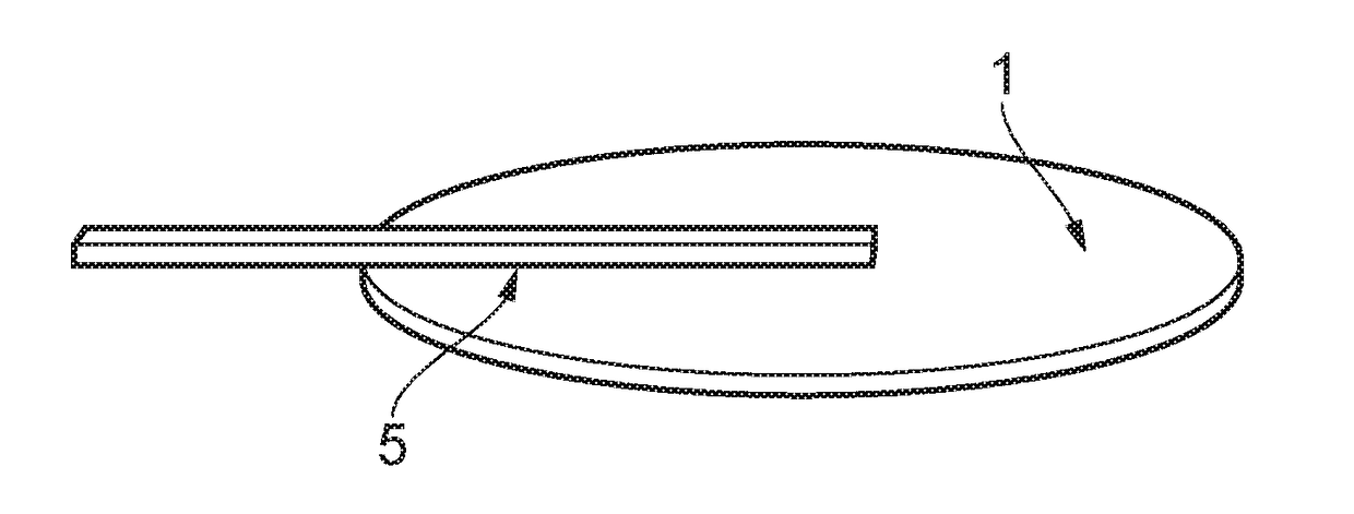
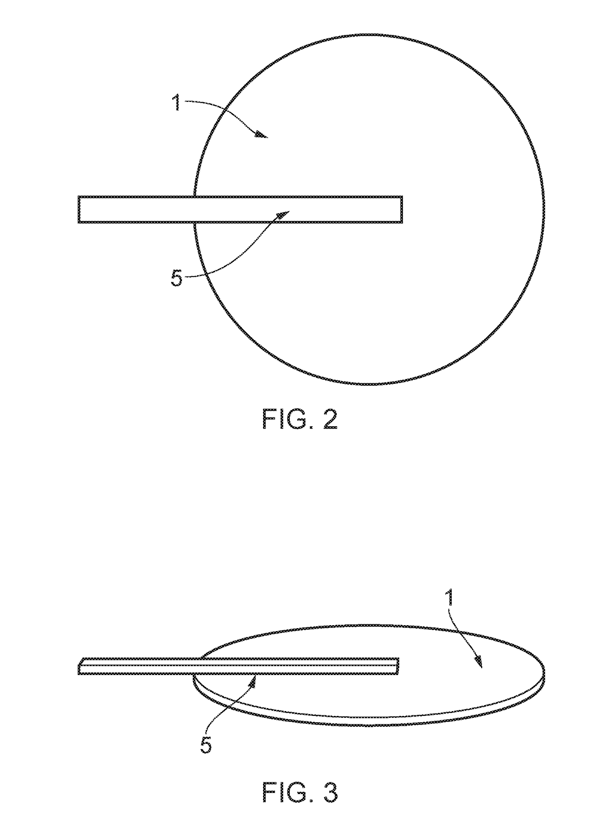
[0013]The electromagnetic waveguide may advantageously be formed integrally with the flexible membrane. Thus the electromagnetic waveguide may be fabricated from substantially the same material as the flexible membrane, as a single piece. This may provide an efficient means for forming the electromagnetic waveguide, and may also ensure that the electromagnetic waveguide and the flexible membrane are firmly connected together. This also simplifies the formation process of the flexible membrane and electromagnetic waveguide, as the flexible membrane and the electromagnetic membrane may be formed together as a unit.
[0014]The flexible membrane may advantageously further comprise a balancing member. The balancing member may be configured to balance the electromagnetic waveguide, such that the behaviour of the flexible membrane is more predictable when the membrane is displaced. The balancing member may also act to strengthen the membrane.
[0015]Where a balancing member is used, the substance or material used to form the flexible membrane and to form the balancing member may be substantially the same substance (which may also be used to form the electromagnetic waveguide). Use of the substantially the same substance to form the flexible membrane and the balancing member provides a good connection between the flexible membrane and the balancing member, and also simplifies the formation process, particularly where the balancing member is formed as a single piece with the flexible membrane.The flexible membrane may be formed from silicon nitride, polyimide, silicon dioxide or polysilicon.
[0016]There is also provided a microelectromechanical system comprising a substrate, the substrate comprising the flexible membrane. By integrating the flexible membrane into a broader system, it is possible to provide a complete sensing apparatus in a comparatively small and inexpensive package.

Problems solved by technology

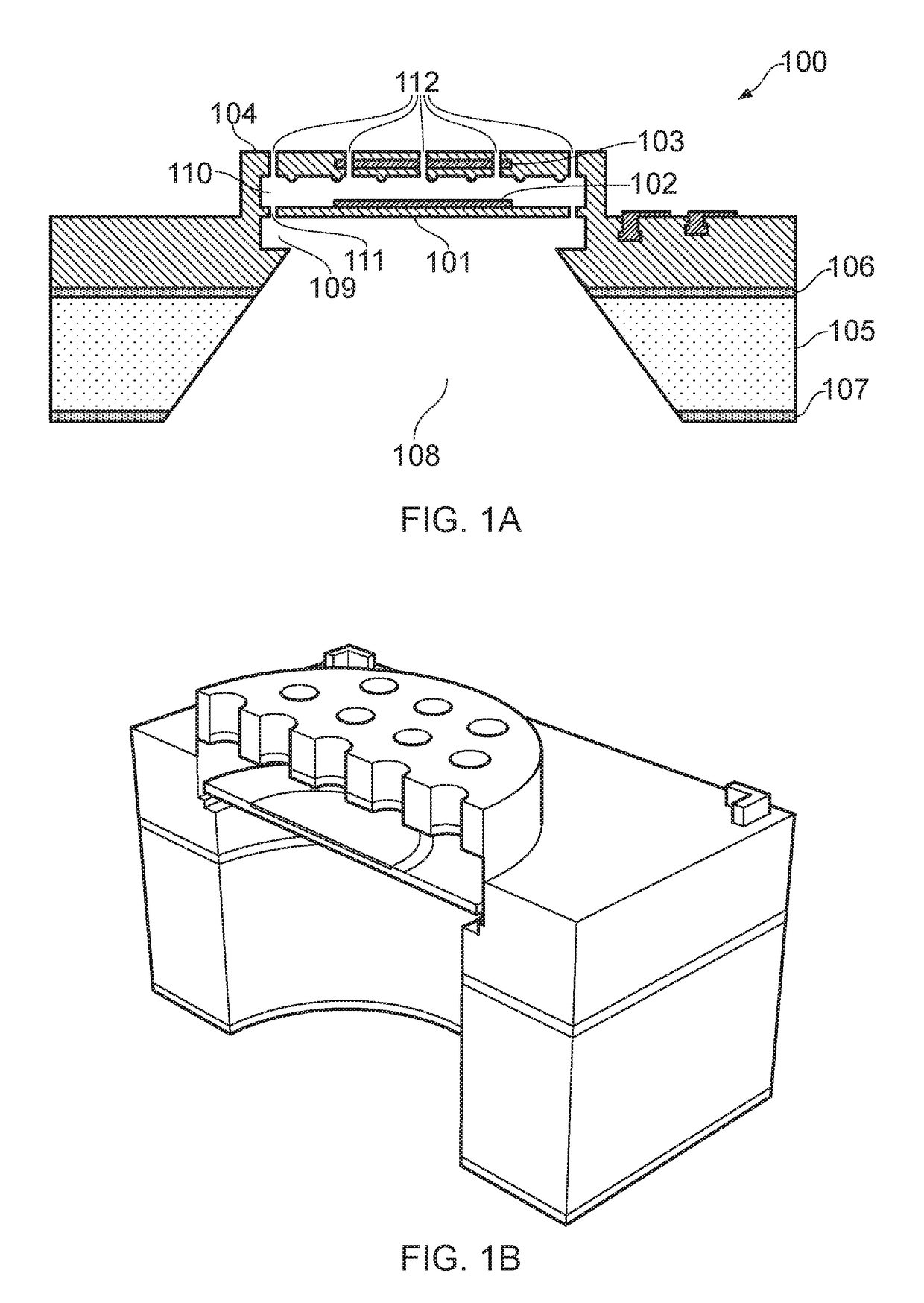
In known MEMS microphone devices, such as the device shown in FIGS. 1A and 1B, the passage of sound through acoustic holes in the back plate may generate noise, reducing the quality of detected sound.
The requirement to provide a back plate electrode of sufficient area to allow the capacitive system to function can also limit the acoustic performance of known MEMS capacitive microphone devices.

Method used


Image

  • Flexible membrane
  • Flexible membrane
  • Flexible membrane

Examples


embodiment 1

Optical Microphone Embodiment 1

[0116]FIG. 11A shows a flexible membrane 1 and electromagnetic waveguide 5 terminating in an electromagnetic wave diverter 6 for use in an optical microphone configuration in accordance with a first optical microphone configuration embodiment (Embodiment 1). The operating principle is shown in FIG. 11B. This example utilises a configuration similar to that of a Fabry-Pérot interferometer. In this example, the light that has propagated along the electromagnetic waveguide is diverted by an electromagnetic wave diverter 6 (not shown in FIG. 11B), such that the electromagnetic wave is emitted from the waveguide. In the example shown in FIG. 11A, the electromagnetic wave diverter is configured to divert the electromagnetic waves through an angle of approximately 90°, such that waves which were previously propagating through the waveguide approximately parallel to a planar surface of the flexible membrane (and along a primary axis of the waveguide) are coupl...

embodiment 2

Optical Microphone Embodiment 2

[0122]In the second optical microphone embodiment (Embodiment 2), the overall configuration of the optical microphone system is similar to that of Embodiment 1. As in Embodiment 1, the light that has propagated along the electromagnetic waveguide is diverted by an electromagnetic wave diverter 6, such that the electromagnetic wave is emitted from the waveguide However, rather than being configured to divert the electromagnetic waves through an angle of approximately 90°, such that waves propagate normal to the plane of the flexible membrane, the diverter 6 is configured to couple the electromagnetic waves out of the waveguide, and thus divert the electromagnetic wave out of the plane of the flexible membrane at an angle other than 90°. The diverted wave propagation vector accordingly has a component parallel to the surface of the flexible membrane, in addition to having a component normal to the surface of the flexible membrane. Therefore, the reflecte...

embodiment 3

Optical Microphone Embodiment 3

[0133]A plan view of a flexible membrane and electromagnetic waveguide in accordance with a third optical microphone configuration embodiment (Embodiment 3) is shown in FIG. 14A. In this embodiment an electromagnetic wave enters the electromagnetic waveguide that is a component of the flexible membrane, as is the case in Embodiments 1 and 2. However, the electromagnetic wave does not encounter a diverter. Instead, the electromagnetic wave is incident upon a planar surface 53 of the electromagnetic waveguide that is perpendicular to the direction of propagation of the electromagnetic wave through the waveguide. This planar surface 53 is then followed (in the direction of propagation of the electromagnetic wave) by a space 55, and then by a contact member 57. In Embodiment 3, the contact member is a further electromagnetic waveguide, however different configurations of contact member can be used, and further embodiments are discussed below. In FIG. 14A, ...


PUM

PropertyMeasurementUnit
wavelengthsaaaaaaaaaa

Abstract

There is provided a flexible membrane for use in a microelectromechanical transducer, the flexible membrane comprising an electromagnetic waveguide. There is further provided a microelectromechanical system comprising a substrate which comprises the flexible membrane, and a process for forming the flexible membrane. The flexible membrane may be configured to operate within an optical microphone system.

Description

[0001]A flexible membrane, and in particular a flexible membrane comprising an electromagnetic waveguide that is suitable for use in a microelectromechanical (MEM) transducer system.BACKGROUND[0002]The use of microelectromechanical systems (MEMS) is becoming increasingly prevalent in electronic devices as the physical size of the devices decreases. One of the driving factors resulting in the increased use of MEMS is the market pressure to provide new devices having the same or greater capabilities as existing devices in a physically smaller enclosure. The drive to produce smaller devices having greater capabilities is particularly strong for consumer electronics devices, such as mobile telephones and laptop computers.[0003]A common example of a MEM device that can be found in a broad range of consumer electronics is a MEMS transducer, for example, a MEMS microphone. These devices can be useful wherever it is necessary to detect sound using a compact device. Typically, MEMS microphon...

Claims


Application Information

Patent Timeline
Patent Type & Authority Applications(United States)
IPC IPC(8): B81B3/00H04R23/00G01H9/00H04R31/00B81C1/00
CPCB81B3/0021H04R23/008G01H9/004H04R31/006B81C1/00158H04R2201/003G01H9/00H04R7/04H04R19/005B81B3/0029B81B2201/0257B81B2201/047B81B2203/0109B81B3/0027B81B7/02B81B2201/04B81B2203/0127
Inventor HOEKSTRA, TSJERK HANS
Owner CIRRUS LOGIC INC
Why Eureka
Try Eureka