
Transmission with a torsion spring and method for operating a transmission

a transmission and torsion spring technology, applied in torsion springs, transmissions, transportation and packaging, etc., can solve the problems of limited-speed switching operation of gearboxes, inability to select the gear ratio, and disadvantage of continuously variable transmissions, so as to achieve no friction, no energy loss, and faster rotational speed

Active Publication Date: 2018-07-26
WEILENMANN MARTIN
View PDF1 Cites 3 Cited by
  • Summary
  • Abstract
  • Description
  • Claims
  • Application Information

AI Technical Summary

Benefits of technology

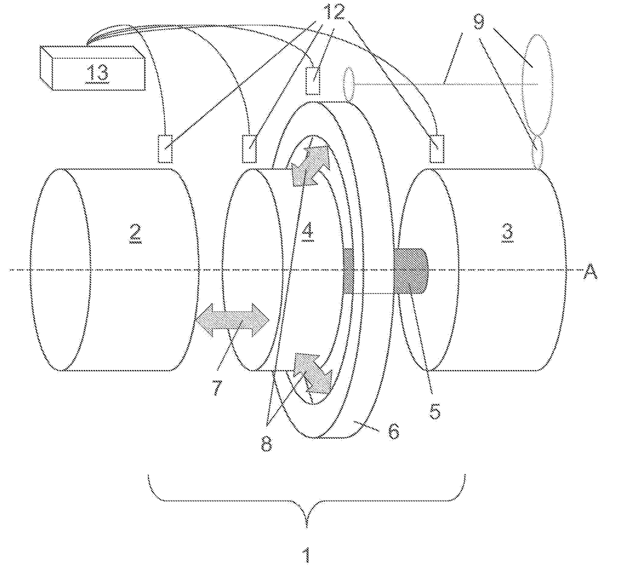
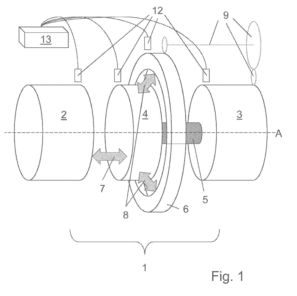
The present invention is a continuously variable, mechatronic transmission that has a simple and reliable design without any friction losses and wear. It uses the fact that a torque subjected to high-frequency changes acts on the inert masses of the drive and output, which results in the same effect as a constant torque. Couplings between the rotating parts are only generated if they have the same rotational speed, and no friction arises in the coupling process. The coupling wheel is connected with the output shaft by torsion springs, so that the coupling wheel can also reach faster rotational speeds than the output shaft by absorbing the energy stored in the torsion spring, in particular the much higher rotational speed of the drive shaft. Overall, the invention provides a smooth and reliable way to establish a coupling between the coupling wheel and also idle support device in a standstill moment.

Problems solved by technology

As a result, it is not always possible to select the gear ratio that is ideal for the given operating point in terms of consumption or efficiency (or other criteria).
In addition, gearboxes have limited-speed switching operations, which are characterized either by tractive effort interruption or lossy dual clutch circuits.
Continuously variable transmissions have this disadvantage.
In summation: Since both the moments of inertia for the drive (engine) and output (vehicle) are not negligible, the continuously variable transmission or its control unit cannot directly set rotational speed ratios.
For example, these irregularities are caused in gear wheels by the elasticity of the teeth or their wear (geometry error) or in chain gears (motorcycles) by the expansion of the links.
Even in continuously variable chain variators, the links entering into the bevel gears can lead to such torque fluctuations.
Based on the above approach, a torque imbalance must be generated at least on one side of the transmission (drive or output) while changing the gear ratio.
The disadvantage to all of these systems is that the force is transmitted through frictional engagement in a punctiform zone when flattened portions are disregarded.
Large contact forces must prevail to prevent slippage, resulting in high loads on the components.
It is further disadvantageous that the gear ratio can only be changed slowly and not at standstill, since the one friction body has to roll onto the other not purely tangentially, as in stationary states, but rather slightly radially, so that the contact point moves to another radius.
During this process, constraint torques develop between the converging disks and the chain (or belt), which contribute to the torque imbalance described above.
As a result, these transmissions have roughly the same disadvantages as the friction gears, specifically a punctiform frictional engagement, which produces high contact pressures and only allows rapid transmission changes to a limited extent.
As mentioned, stepped transmissions cannot represent any gear ratios desired.
All known mechanical, continuously variable transmissions have the disadvantage that the force is transmitted via friction in a punctiform or linear zone, which translates into high contact forces, and hence a high surface load for the components.
In particular the drivetrains of road vehicles are in practice exposed to frequent and very quickly changing loads.
The described transmission has a complicated structural design, wherein it is unclear how the output shaft can be reliably driven in a controlled manner.
As mentioned in the text, a rotational speed that depends on the load, i.e., the load torque, on the output arises at the output at a constant rotational speed of the drive, which is disadvantageous.
U.S. Pat. No. 2,864,259 is characterized by the use of passive freewheel clutches, which do not allow any couplings at freely selectable points in time.

Method used


Image

  • Transmission with a torsion spring and method for operating  a transmission
  • Transmission with a torsion spring and method for operating  a transmission
  • Transmission with a torsion spring and method for operating  a transmission

Examples


Embodiment Construction

[0034]The object of the present invention is to indicate a continuously variable, mechatronic transmission of the kind described at the outset that has a simple and reliable structural design, and in which no friction losses and wear arise due to grinding couplings or punctiform transmissions via chains or belts. This invention utilizes the aforementioned fact that a torque subjected to high-frequency changes that acts on the inert masses of the drive (e.g., crankshaft of an internal combustion engine) and output (drivetrain and vehicle) essentially has the same effect as a constant torque, which corresponds to the chronologically average value of the torque undergoing high-frequency changes.

[0035]Another object of the invention is to describe a method in which power is transmitted by means of such a mechatronic transmission.

[0036]The object is achieved by the distinguishing characteristic in the independent claims. Preferred devices are indicated in the subclaims.

[0037]The idea of ...


PUM


Abstract

A mechatronic transmission for transmitting a torque from the drive shaft that can be supported axially on a shaft to an output shaft, the rotational speeds of which can have an arbitrary and variable ratio (stepless transmission). The transmission includes a coupling gear and a torsion spring, with the coupling gear rotatably mounted on the same shaft and connected to the output shaft by the torsion spring, and having a first coupling for producing and cancelling a rotationally fixed, planar, force-fitting first coupling between the drive shaft and the coupling gear. The transmission comprises a supporting device which is rotatable having a fixed transmission ratio of 1:X relative to the output shaft, where X can be any real number between approximately −10 and 1, and a second coupling for producing and cancelling a rotationally fixed, force-fitting second coupling between the supporting device and the coupling gear.

Description

TECHNICAL AREA[0001]The invention relates to a transmission for transmitting a torque or power from a drive shaft that can be axially supported on a shaft to an output shaft given an continuously variable transmission ratio, comprising a coupling wheel and a torsion spring, wherein the coupling wheel is rotatably mounted on the same shaft and can be connected with the output shaft by the torsion spring, and also comprising a first coupling means for generating and canceling a rotationally fixed, planar, force-fitting first coupling between the drive shaft and coupling wheel. The invention also relates to a method for operating a transmission.PRIOR ART[0002]In most applications for engines, the favorable operating ranges of the latter in terms of speed and torque do not lie within the range of the application, which necessitates gearing or transmissions.[0003]Fixed gearings and gearboxes are mostly based on rack-and-pinion constructions in wide-ranging variants or on gear-chain trans...

Claims


Application Information

Patent Timeline
IPC IPC(8): F16F1/14F16H33/08B60G21/055B60G11/20
CPCF16F1/145F16H33/08B60G21/0556B60G11/20F16H2706/00B60G2204/122B60G2206/012F16H33/02F16F1/14
Inventor WEILENMANN, MARTIN
Owner WEILENMANN MARTIN
Learn More