
Integral Plastic Ball Valve For Fluid Transmission And Manufacturing Process

a technology of fluid transmission and manufacturing process, applied in valve housings, other domestic objects, mechanical instruments, etc., can solve the problems of low qualified product rate, low product rejection rate, and relatively poor pressure resistance strength of integrally molded structures, and achieve consistent reliability in the quality of functions, easy manufacturing, and greater accuracy

Inactive Publication Date: 2018-07-26
YELKEN DOUG
View PDF8 Cites 4 Cited by
  • Summary
  • Abstract
  • Description
  • Claims
  • Application Information

AI Technical Summary

Benefits of technology

The present invention introduces an improved method of manufacturing ball valves for fluid transmission through pipelines. The invention utilizes an integral plastic ball valve that is securely fixed inside a valve housing, resulting in a more durable and reliable product. The manufacturing process involves injection molding, which provides greater accuracy and tolerance dimensions as compared to traditional methods that use individual technicians. The overall effect is a better performing and reliable ball valve assembly.

Problems solved by technology

CN201836497U comprises a valve housing that is assembled by welding and has relatively poorer pressure resistant strength compared with an integrally molded structure.
The assembly by welding is apt to cause its valve ports at both ends to be asymmetrical and not concentric with each other, resulting in high product rejection rate, low qualified product rate, low productivity, and high production costs.
However, the valve core is too simple in structure and has some defects.

Method used


Image

  • Integral Plastic Ball Valve For Fluid Transmission And Manufacturing Process
  • Integral Plastic Ball Valve For Fluid Transmission And Manufacturing Process
  • Integral Plastic Ball Valve For Fluid Transmission And Manufacturing Process

Examples


Embodiment Construction

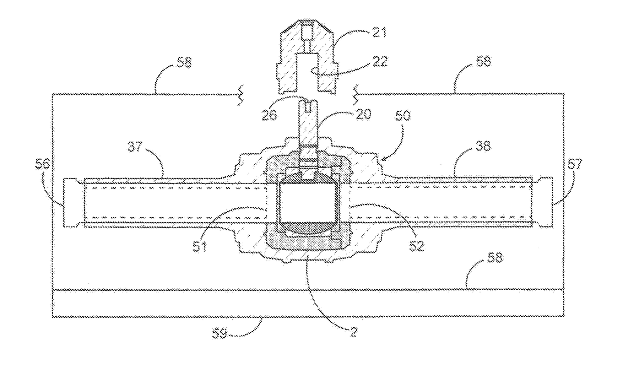
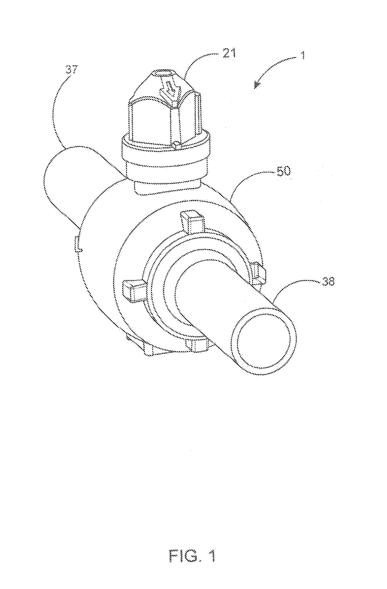
[0054]The inventive concept disclosed herein features a ball valve that is manufactured by a method comprising injection molding. An understanding of the inventive concept is best conveyed by reference to the accompanying drawing figures, of which there are seventeen in number. A step-by-step tracking of the process of manufacturing, the ball valve 1 provides a thorough explanation of the particular injection molding process. Starting with FIG. 1, there is presented a completely assembled ball valve 1, with the valve body housing 50, and integral inlet and / or outlet pipes 37, 38, the outlet pipes 37, 38 having been fabricated during the injection molding process. Also shown is the ball valve 1 control handle 21 for setting the direction and volume of the flow of internally transmitted fluids and for shutting off the fluid flow.

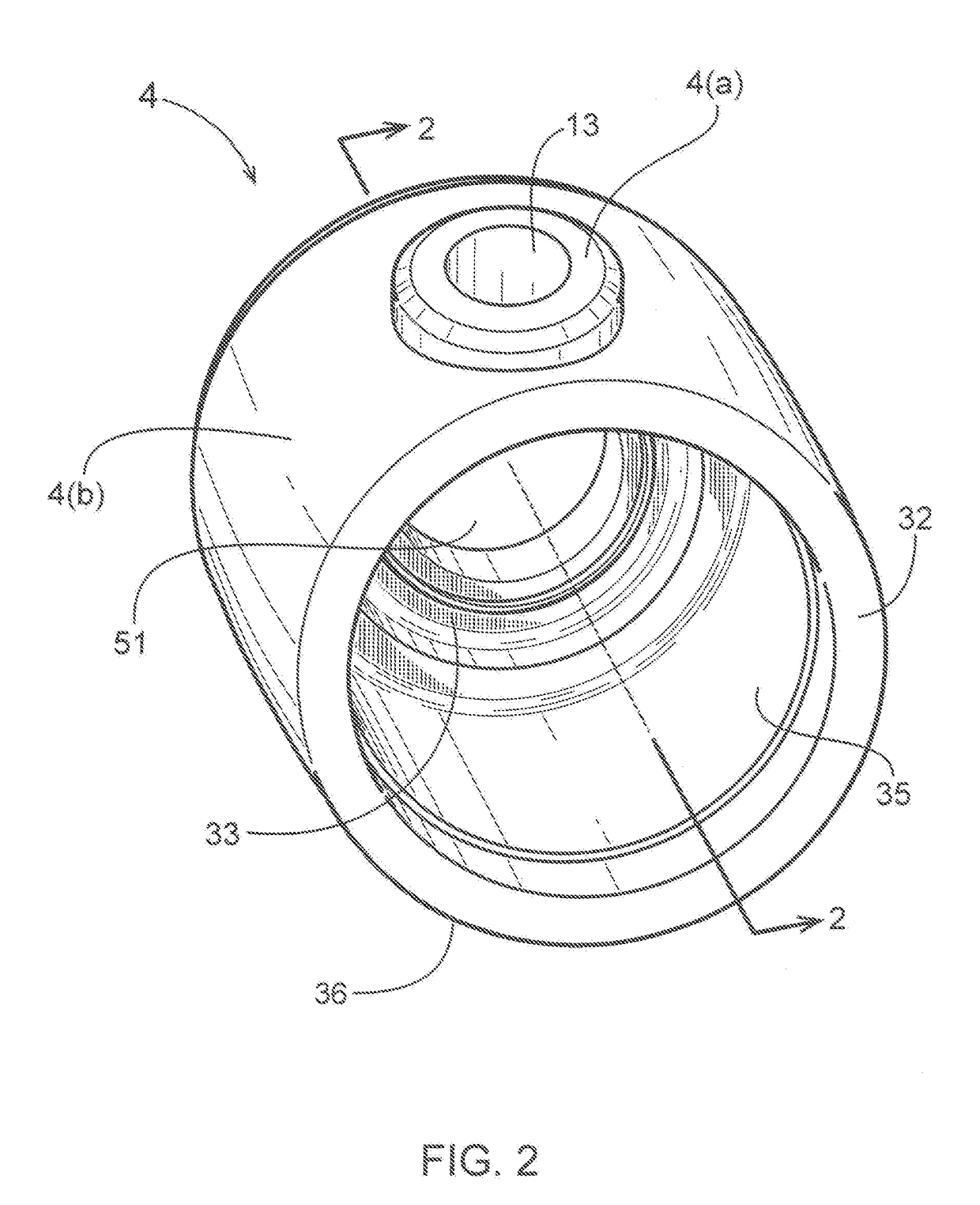
[0055]The primary component, of the ball valve 1 assembly is the spherical enclosure 4, which is shown in perspective in FIG. 2. The spherical enclosure 4 is ...


PUM

PropertyMeasurementUnit
inner diameteraaaaaaaaaa
outer diameteraaaaaaaaaa
dimensionsaaaaaaaaaa

Abstract

The inventive concept discloses a completely integral ball valve manufactured by an injection molding process. The device comprises a valve core, a valve housing, a valve control handle, and inlet / outlet flow pipes, all forming an integral structure. The valve core is the primary component of the ball valve, and is comprised of a spherical enclosure, a valve ball, left and right leakage seal rings, a spherical enclosure cap, a valve stem affixed to the valve ball, and a valve handle. The valve core, valve housing, and left and right intake / outflow pipes are integrally assembled by injection molding. The injection molding process gives the ball valve higher flexion strength and greater durability as compared to the typical sweat soldering process. Precisely dimensioned mold sections ensure the accuracy of dimensions, fittings, and tolerances of the ball valve components during the injection molding. Primary materials used are polypropylene and high-density polyethylene

Description

CROSS-REFERENCES- TO RELATED APPLICATIONS[0001]This is a continuation-in-part patent application which claims the benefit and priority of parent U.S. Published patent application Ser. No. 14 / 262,726 filed on Apr. 26, 2014, and currently co-pending before the USPTO, by reference as though said parent application Ser. No. 14 / 262,726 appears fully herein.STATEMENT REGARDING FEDERALLY SPONSORED RESEARCH OR DEVELOPMENT[0002]Not applicable.NAMES OF THE PARTIES TO A JOINT RESEARCH AGREEMENT[0003]Not applicable.[0004]BACKGROUND OF THE INVENTION(1) Field of the Invention[0005]The inventive concept disclosed is involved with valve control mechanisms and systems used in controlling the transmission of fluids such as water, liquefied gas, petroleum, and other substances through pipelines. The inventive concept further includes manufacture utilizing an injection molding process of a ball valve useful for such purposes.[0006](2) Description of the Related Art, Including Information Disclosed Unde...

Claims


Application Information

Patent Timeline
Patent Type & Authority Applications(United States)
IPC IPC(8): F16K5/06B23P15/00B29C45/14B29C45/00B29C45/26B29C45/73B29C45/40
CPCF16K5/0657B23P15/001F16K5/0605F16K5/0642F16K5/0647F16K5/0689F16K5/0694B29C45/14065B29C45/14754B29C45/0053B29C45/26B29C45/73B29C45/40B29K2623/12B29K2023/06B29K2705/12B29K2661/00B29K2659/00B29L2031/7506B29C45/261F16K27/067B29C2045/14131
Inventor YELKEN, DOUG
Owner YELKEN DOUG
Learn More