Hydrogen gas burner device

a burner device and hydrogen gas technology, applied in the direction of lighting and heating apparatus, combustion regulation, combustion types, etc., can solve the problem that the quantity of heat of the heated fuel gas is not taken into account in the quantity of heat needed, and achieve the effect of further reducing the concentration of nox generated during combustion, further widening the combustion region of hydrogen gas, and reducing the temperature rise of the flame portion

Active Publication Date: 2018-08-09
TOYOTA JIDOSHA KK
View PDF0 Cites 2 Cited by
  • Summary
  • Abstract
  • Description
  • Claims
  • Application Information

AI Technical Summary

Benefits of technology

[0006]Meanwhile, in a case where hydrogen gas is used for the fuel gas, the combustion speed of the hydrogen gas is higher than that of other fuel gas. Therefore, the combustion of the hydrogen gas progresses at a time before the hydrogen gas is diffused. Particularly, in a case where the hydrogen gas is heated as in the gas burner device of JP 2016-166683 A, the combustion speed of the hydrogen gas increases. For this reason, the temperature of a flame portion of the combusted hydrogen gas tends to be higher than that of a flame portion of combusted town gas or the like, NOx is generated by an oxidation reaction of N2 in the air, and a relatively large amount of NOx is easily contained in an exhaust gas after combustion.
[0007]The present disclosure provides a hydrogen gas burner device that can supply hydrogen gas with a flow rate optimal for a needed quantity of heat to a combustion nozzle and that can further reduce the concentration of NOx generated by the combustion of the hydrogen gas.
[0012]The hydrogen gas is released from the combustion nozzle by the flow speed regulator such that the flow speed of the hydrogen gas increases when the flow rate of the hydrogen gas passing through the flow rate regulator decreases. That is, since the hydrogen gas heated to a higher temperature is released from the combustion nozzle at a higher flow speed, a combustion region of the hydrogen gas can be further widened. As a result, the temperature rise of a flame portion can be further suppressed, and the concentration of NOx generated during combustion can be further reduced.

Problems solved by technology

However, in a case where the fuel gas before combustion is heated in advance as in the gas burner device of JP 2016-166683 A, the quantity of heat of the heated fuel gas is not taken into consideration with respect to a needed quantity of heat.

Method used


Image

  • Hydrogen gas burner device
  • Hydrogen gas burner device
  • Hydrogen gas burner device

Examples


first embodiment

[0023]1. Hydrogen Gas Burner Device 1

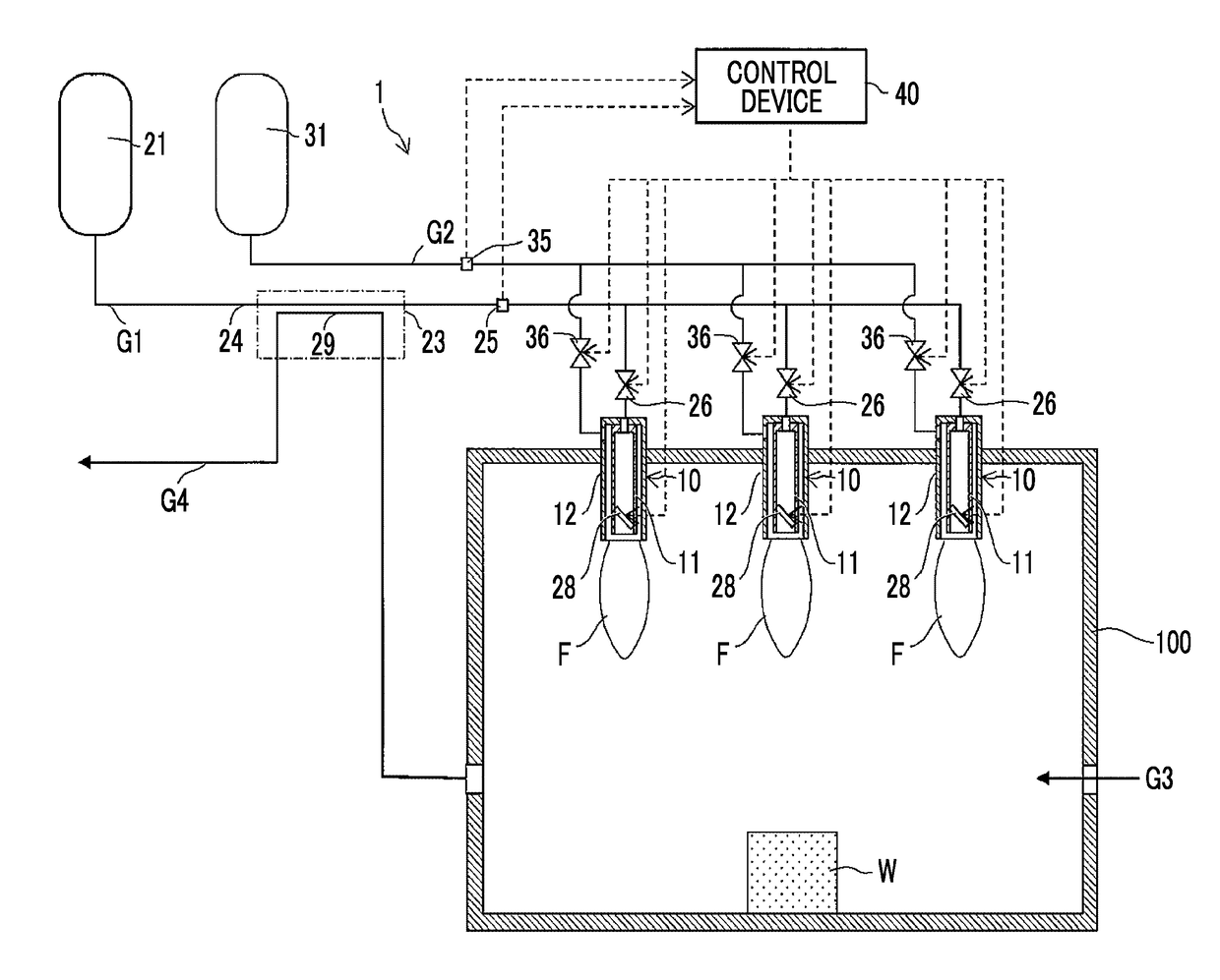
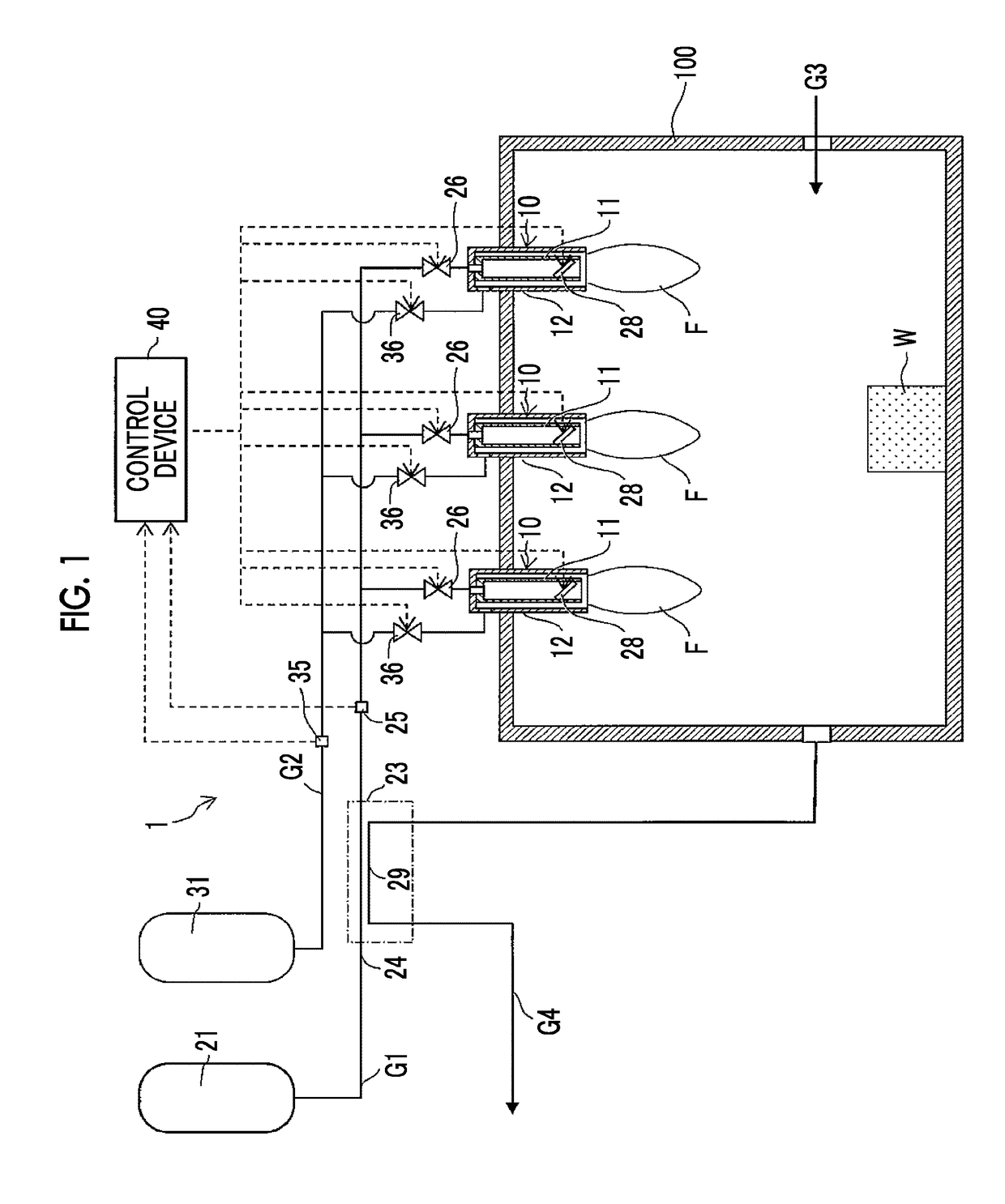
[0024]FIG. 1 is a schematic conceptual diagram of a hydrogen gas burner device (hereinafter, a gas burner device) 1 related to the present embodiment, and is an example in which the gas burner device 1 is applied to a heating furnace 100 that heats a workpiece W through the combustion of hydrogen gas G1. As illustrated in FIG. 1, the gas burner device 1 related to the first embodiment is a device using the hydrogen gas G1 as fuel, and includes a combustion nozzle 10 to which the hydrogen gas G1, and a combustion-supporting gas G2 containing oxygen gas, are supplied.

[0025]Specifically, in the present embodiment, three combustion nozzles 10 are attached to an upper part of the heating furnace 100, and flames F are generated by igniting the hydrogen gas G1 released into the heating furnace 100 from the combustion nozzles 10.

[0026]In the present embodiment, the gas burner device 1 includes a hydrogen gas supply source 21, a heat exchanger (gas heater...

second embodiment

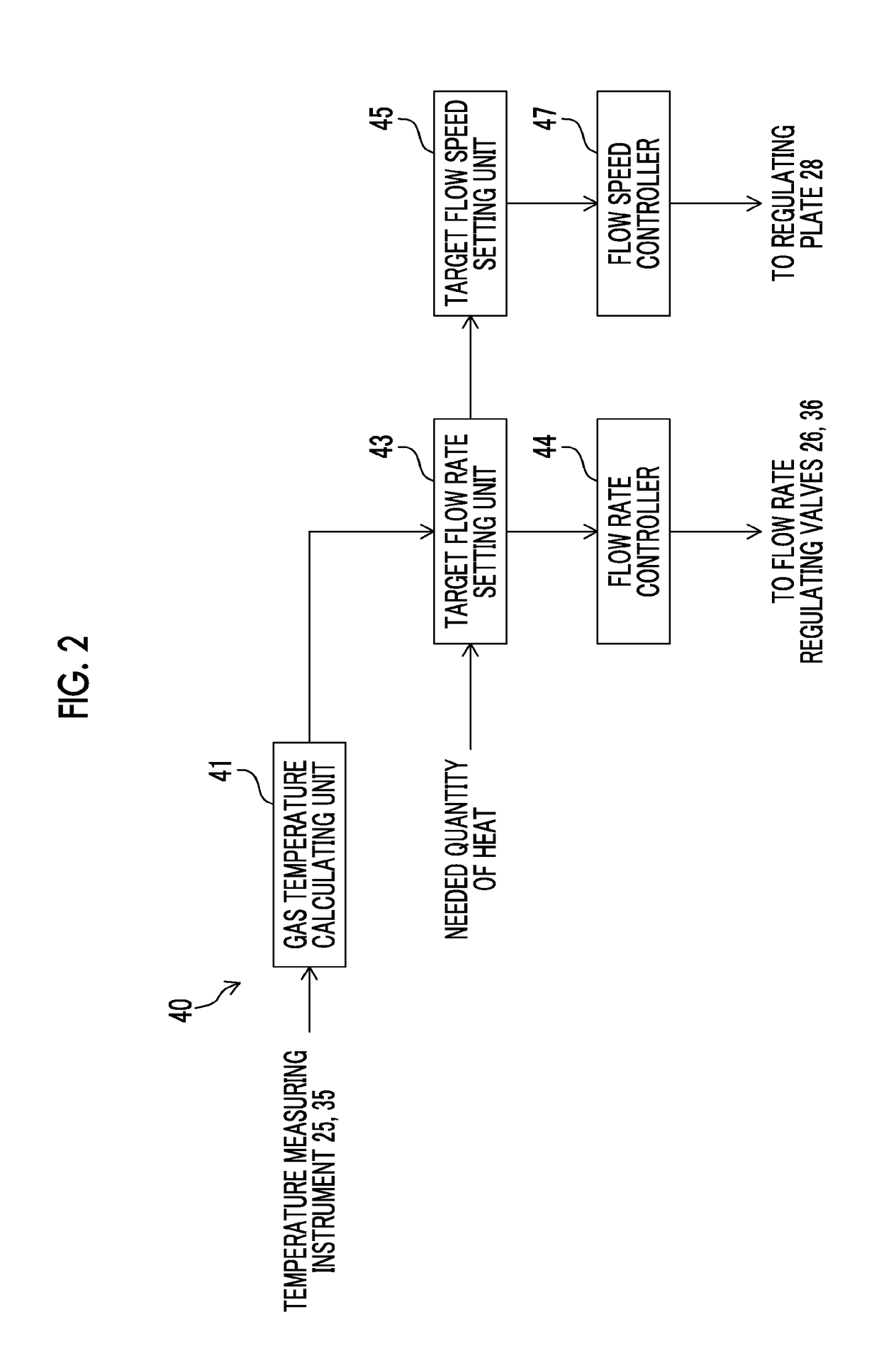
[0064]FIG. 5 is a schematic conceptual diagram of a gas burner device 1 related to a second embodiment. FIG. 6 is a block diagram of a control device 40 of the gas burner device 1 illustrated in FIG. 5. The gas burner device 1 related to the second embodiment is different from that of the first embodiment in that the combustion-supporting gas G2 is further heated by the heat exchanger 23, the temperature regulating valves 22, 32 are provided, and control is performed by the control device 40. Hereinafter, solely differences will be described, and other portions will be designated by the same reference signs as those of the gas burner device 1 of the first embodiment and the detailed description thereof will be omitted.

[0065]As illustrated in FIG. 5, the heat exchanger 23 of the gas burner device 1 related to the present embodiment also heats the combustion-supporting gas G2 flowing into a pipe 34 with the heat of the exhaust gas G4. The gas burner device 1 includes the temperature r...


PUM


Abstract

A control device of a hydrogen gas burner device sets a target flow rate of a hydrogen gas such that a flow rate of the hydrogen gas decreases as a temperature of the hydrogen gas becomes higher, based on the temperature of the hydrogen gas and a needed quantity of heat of the hydrogen gas during the combustion, sets a target flow speed such that the flow speed of the hydrogen gas released from a combustion nozzle via a flow speed regulator becomes a flow speed based on the target flow rate and the flow speed of the hydrogen gas increases as a value of the target flow rate decreases, controls the flow rate regulator such that the flow rate of the hydrogen gas reaches the target flow rate, and controls the flow speed regulator such that the flow speed of the hydrogen gas reaches the target flow speed.

Description

INCORPORATION BY REFERENCE[0001]The disclosure of Japanese Patent Application No. 2017-021250 filed on Feb. 8, 2017 including the specification, drawings and abstract is incorporated herein by reference in its entirety.BACKGROUND1. Technical Field[0002]The present disclosure relates to a hydrogen gas burner device using hydrogen gas for fuel gas.2. Description of Related Art[0003]In the related art, burner devices that generate flames by igniting combustible fuel with an ignition device have been suggested. For example, Japanese Unexamined Patent Application Publication No. 2013-029265 (JP 2013-029265 A) suggests a burner device that includes a fuel nozzle which sprays fuel and that regulates the flow rate of the fuel jetted from the fuel nozzle by controlling the aperture of the fuel nozzle.[0004]Japanese Unexamined Patent Application Publication No. 2016-166683 (JP 2016-166683 A) suggests a gas burner device that generates flames by igniting air-fuel mixture, in which combustion a...

Claims


Application Information

Patent Timeline
Patent Type & Authority Applications(United States)
IPC IPC(8): F23N1/00F23N5/14
CPCF23N1/002F23N5/143F23N2021/06F23N2039/04F23N2021/08F23D14/22F23D14/60F23D14/66F23C2900/9901F23K5/007F23N2221/06F23N2221/10F23K2400/10F23K2400/201Y02E20/34F23K5/002F23K5/005F23N1/005F23N1/022F23N1/025F23N2221/08F23N2239/04
Inventor MIMURA, KENSHIRO
Owner TOYOTA JIDOSHA KK
Why Eureka
Try Eureka