Power converter and method of control thereof

Active Publication Date: 2018-08-09
DELTA ELECTRONICS INC
View PDF4 Cites 33 Cited by
  • Summary
  • Abstract
  • Description
  • Claims
  • Application Information

AI Technical Summary

Benefits of technology

[0007]The present invention provides a flyback power converter with a hybrid clamp circuit (i.e., a combined circuit having both passive RCD circuit and active clamp circuit properties), and a corresponding power management unit that substantially optimizes the performance of the flyback power converter in its entire line and load ranges. According to one embodiment of the present invention, the clamp circuit, which is connected in parallel to a primary winding of the flyback transformer, includes a parallel combination of a capacitor and resistor that is connected in series with a parallel combination of a switch and a dio

Problems solved by technology

As silicon-based devices approach their theoretical performance limits, fur

Method used


Image

  • Power converter and method of control thereof
  • Power converter and method of control thereof
  • Power converter and method of control thereof

Examples


Embodiment Construction

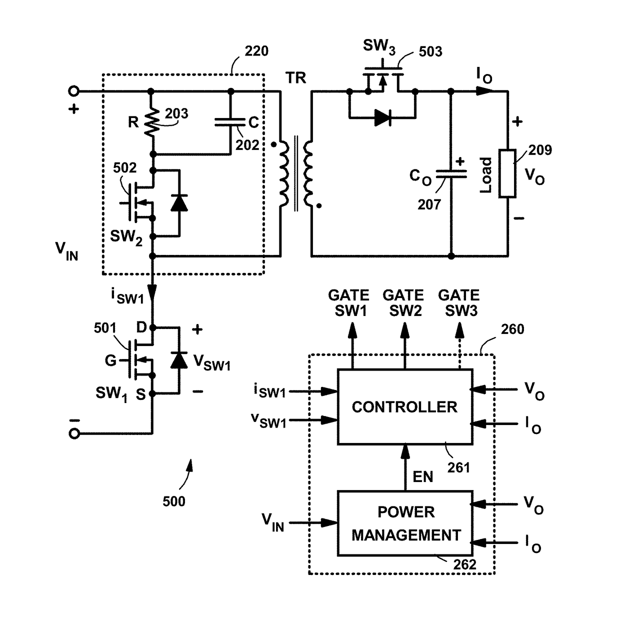
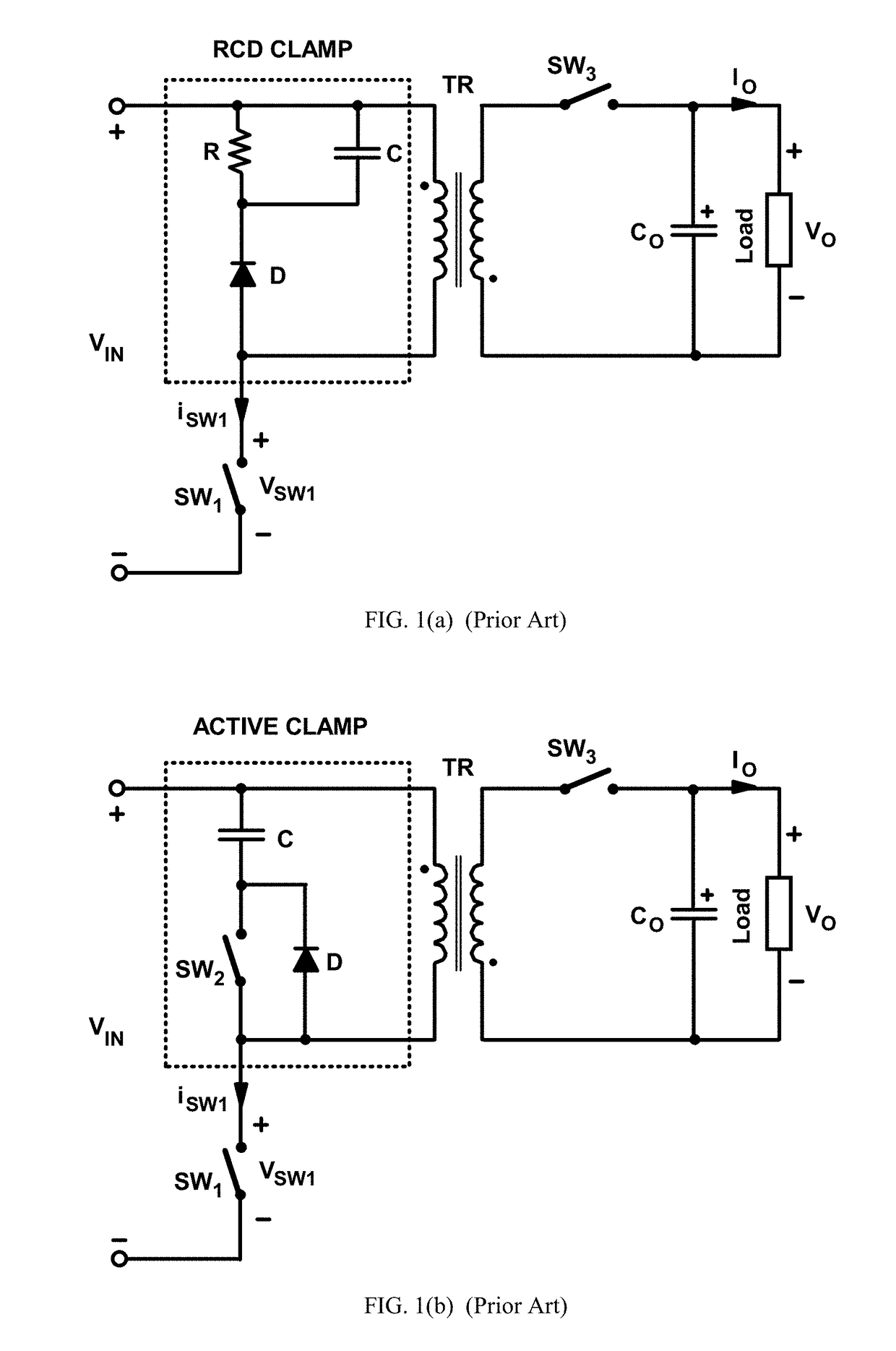
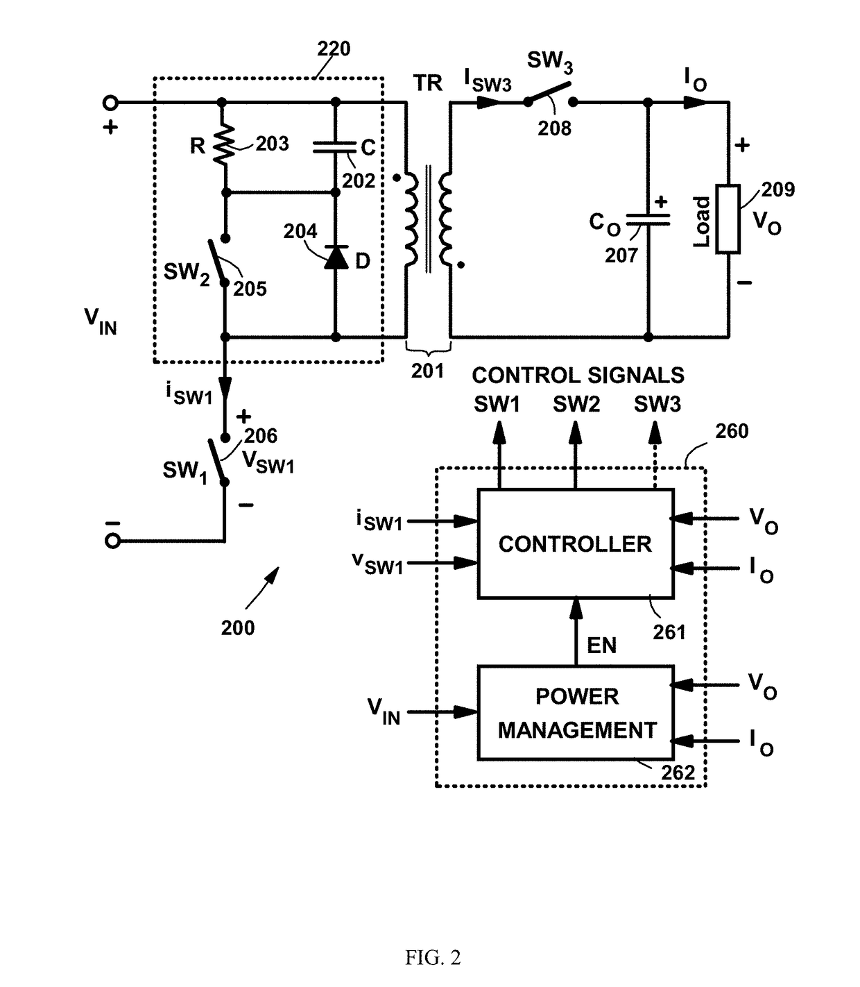
[0024]FIG. 2 is a circuit diagram of flyback converter 200 with hybrid clamp circuit 220, according to one embodiment of the present invention. As shown in FIG. 2, hybrid clamp circuit 220, which is connected in parallel with primary winding 201a of flyback transformer 201, includes a parallel combination of capacitor 202 and resistor 203 that is connected in series with a parallel combination of switch 205 and diode 204. FIG. 2 also shows control block 260, which includes controller 261 and power management unit 262. It should be noted that controller 261 and power management unit 262 can be implemented by hardware, software, or any combination of hardware and software. Generally, a hardware implementation includes analog and digital circuits, while a software implementation includes one or more microcontrollers, digital-signal processors, or both, that execute the algorithms that constitute controller 261 and power management unit 262.

[0025]Controller 261 provides control signals ...


PUM


Abstract

A flyback power converter includes a hybrid clamp circuit and a corresponding power management unit that substantially optimizes the performance of the flyback power converter in its entire line and load ranges. The clamp circuit, which is connected in parallel to a primary winding of the flyback transformer, includes a parallel combination of a capacitor and resistor that is connected in series with a parallel combination of a switch and a diode. By sensing the operating conditions, the power management circuit configures the clamp circuit either as a passive clamp or as an active clamp. In the passive-clamp configuration, the switch is kept turned off. In the active-clamp configuration, the switch operates with pulse-width modulation (PWM) which enables ZVS turn-on of the main switch.

Description

BACKGROUND1. Field of the Invention[0001]The present invention relates to a power management and control method of optimizing performance of power converters, in particular, the flyback converter.2. Description of the Related Art[0002]The use of wide-band-gap semiconductor devices and the demand for size reduction in today's external power supplies (e.g., adapters or chargers for laptops, tablets, mobile devices, game consoles, and printers) continue to drive substantial development and research efforts in high-efficiency and high-power-density power conversion technology. Generally, the size of a switch-mode power supply can be reduced by increasing the switching frequency because the sizes of passive components (e.g., transformers, input and output filters) can be reduced at a higher switching frequency.[0003]As silicon-based devices approach their theoretical performance limits, further performance improvements of power supplies have become more difficult. However, emerging wide-...

Claims


Application Information

Patent Timeline
IPC IPC(8): H02M3/335H02M1/32H02M1/08
CPCH02M3/33569H02M3/33592H02M2001/0048H02M2001/0009H02M1/32H02M1/34Y02B70/10H02M1/0054H02M1/344H02M1/0009H02M1/0048
Inventor SONG, HAIBINHUBER, LASZLOXU, DAOFEIZHANG, ALPHAJOVANOVIC, MILAN M.CHANG, CHIEN-CHUNG
Owner DELTA ELECTRONICS INC
Why Eureka
Try Eureka