

Apparatus and method for reverse osmosis
a reverse osmosis and apparatus technology, applied in reverse osmosis, membrane technology, membranes, etc., can solve the problems of reducing the specific energy consumption of products, reducing the osmotic pressure differential, and unsuitable for human consumption without treatment, etc., to achieve the effect of reducing the specific energy consumption (sec), reducing the osmotic pressure differential, and high product recovery
- Summary
- Abstract
- Description
- Claims
- Application Information
AI Technical Summary
Benefits of technology
Problems solved by technology
Method used
Image

Examples
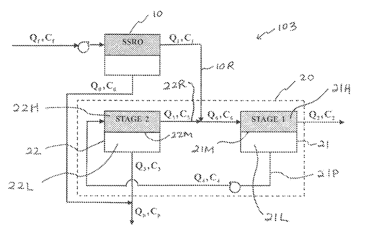
embodiment 103
[0057]The overall recovery YT for the three-stage embodiment 103 of the present EERO invention is determined from the potable water produced by the SSRO unit 10 and that produced by the CMCR unit 20, and is given by the following:
YT=YSSRO+Q3(1−YSSRO) (28)
[0058]The SEC for the three-stage embodiment 103 of the EERO invention is determined from the pumping requirement for the SSRO unit 10, the pumping requirement for the permeate recycle stream 21P in the CMCR unit 20, and the overall water recovery, and is given by the following:
SEC=1+Q4(1-YSSRO)YSSRO+Q3(1-YSSRO)Δπ(29)
[0059]The rejection in stage 1 (21) and the rejection in stage 2 (22) for the three-stage embodiment 103 of the EERO invention are given by the following:
σ1=C6+C2-2C4C6+C2(30)σ2=C4+C5-2C3C4+C5(31)
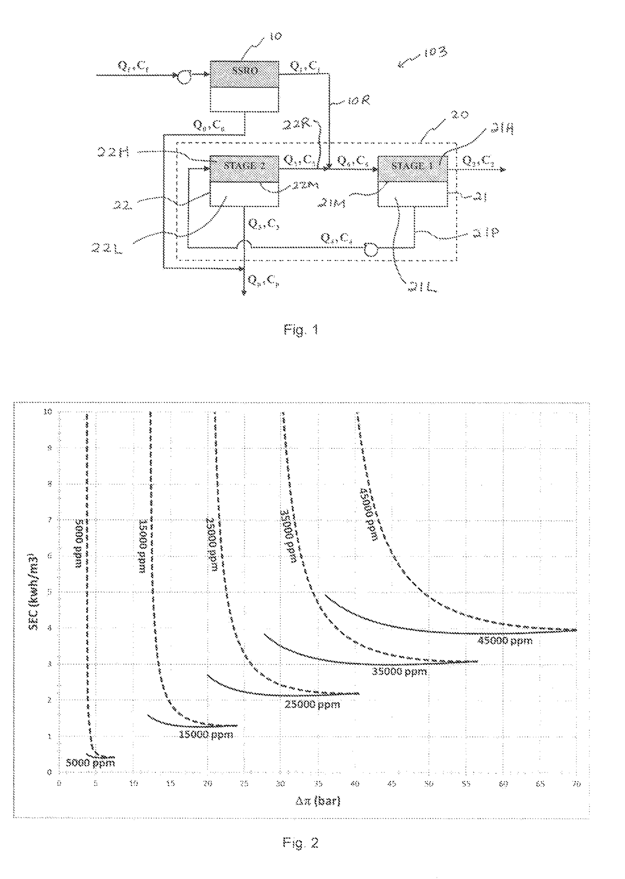
[0060]Solid lines in FIG. 2 are a plot of the SEC predicted by Equation (29) as a function of the OPD, Δπ, for a range of values of the feed concentration to the SSRO unit 10, Cf, for the three-stage embodiment 103 of the pre...
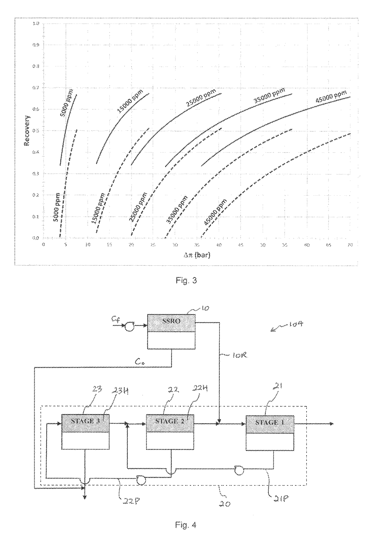
embodiment 104
[0068]The solid lines in FIG. 5 are a plot of the SEC predicted for the four-stage embodiment 104 of the present EERO invention as a function of the OPD, Δπ, for a range of values of the feed concentration, Cf, to the SSRO unit 10. The range of OPD for which the predictions are shown again is limited at some high value when the safety factor in the SSRO stage 10 of the EERO becomes less than one and at some low value of the OPD when the SSRO unit 10 can no longer achieve the specified potable water product concentration, C0, for the specified saline water feed concentration, Cf. As a basis of comparison the dashed lines in FIG. 5 again show the SEC for conventional SSRO alone predicted by Equation (5) as a function of the OPD, Δπ, for the same range of values of the feed concentration, Cf. The range of OPD for which the predictions for conventional SSRO is again limited at some high value when the safety factor becomes less than one and at some low value of the OPD when the conventi...
PUM
 Abstract
Description
Claims
Application Information