Control device for internal combustion engine and control method for internal combustion engine

Active Publication Date: 2018-08-30
TOYOTA JIDOSHA KK
View PDF0 Cites 4 Cited by
  • Summary
  • Abstract
  • Description
  • Claims
  • Application Information

AI Technical Summary

Benefits of technology

[0005]One well-known measure to restrain the generation of condensed water is to increase a temperature of an intake air gas (the fuel mixture) to be higher than the dew point. When the EGR rate becomes high, the dew point becomes high due to an increase in an amount of moisture content included in the intake gas. Accordingly, when the EGR rate is increased, a value of an intake gas temperature to be required to restrain the generation of condensed water increases. When the intake gas temperature increases, knocking easily occurs in a heavy load region. When an ignition timing is retarded to restrain knocking, thermal efficiency decreases.
[0006]Accordingly, under the common general technical knowledge at the time of filing of the present application, it was difficult to sufficiently increase the EGR rate while balancing restraint of generation of condensed water with restraint of knocking. In this regard, due to diligent studies of inventor(s) of the present disclosure, the following finding was obtained. That is, it was found that, with the use of a “high EGR rate” of 25% or more, it is possible to improve thermal efficiency even under a high intake gas temperature, while restraining knocking at the same level as a case under a low intake gas temperature.
[0007]In the meantime, in the hea

Problems solved by technology

When condensed water is generated, a problem such as corrosion of an intake passage wall might occur.
When the intake gas temperature increases, knocking easily occurs in a heavy load region.
Accordingly, under the common

Method used


Image

  • Control device for internal combustion engine and control method for internal combustion engine
  • Control device for internal combustion engine and control method for internal combustion engine
  • Control device for internal combustion engine and control method for internal combustion engine

Examples


Example

[0034]First, with reference to FIGS. 1 to 7, the following describes Embodiment 1 of the present disclosure.

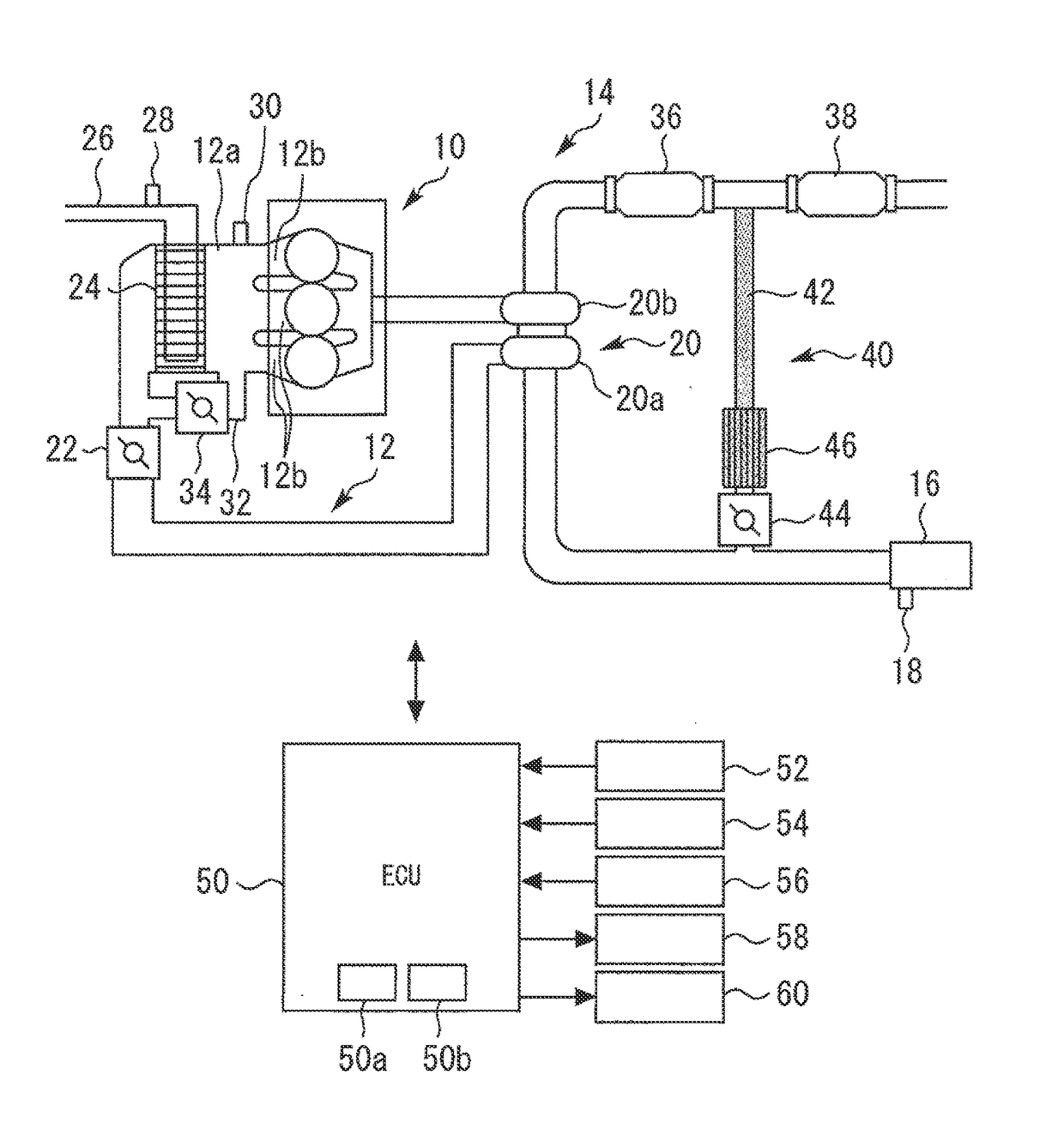
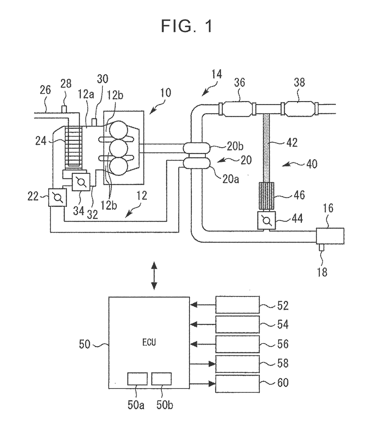
[0035]System Configuration in Embodiment 1 FIG. 1 is a view to describe a system configuration of Embodiment 1 of the present disclosure. A system illustrated in FIG. 1 includes a spark-ignition internal combustion engine 10. The internal combustion engine 10 is an in-line three-cylinder engine as an example. An intake passage 12 and an exhaust passage 14 communicate with each cylinder of the internal combustion engine 10.

[0036]An air cleaner 16 is attached to a vicinal area of an inlet of the intake passage 12. The air cleaner 16 is provided with an airflow sensor 18 configured to output a signal corresponding to a flow rate of an intake gas (air) flowing through the intake passage 12.

[0037]The internal combustion engine 10 includes a turbosupercharger 20 as an example of a supercharger for supercharging an intake air. A compressor 20a of the turbosupercharger 20 is placed in...

Example

[0097]System Configuration in Embodiment 2 In the following description, the configuration illustrated in FIG. 1 is used as an example of a system configuration of Embodiment 2.

[0098]As described in Embodiment 1, a change of the actual EGR rate with respect to a change of the target EGR rate delays during the transient operation. In the LPL-type EGR device 40 having a long passage length from the EGR gas inlet to the cylinder, such a delay is large.

[0099]The present embodiment is targeted for an example in which the low EGR rate region is shifted to the high EGR rate region at the time of a transient operation along with an acceleration request (hereinafter referred to as “acceleration transition”). In this example, the actual EGR rate becomes insufficient with respect to the target EGR rate because of the delay. Meanwhile, a change of the intake gas temperature by a cooler bypass mechanism is quick. Accordingly, when the I / C bypass valve 34 is opened immediately with disregard to t...

Example

[0125]System Configuration of Embodiment 3 In the following description, the configuration illustrated in FIG. 1 is used as an example of a system configuration of Embodiment 3.

[0126]The present embodiment is targeted for an example in which the high EGR rate region is shifted to the low EGR rate region at the time of a transient operation along with a deceleration request (hereinafter referred to as a “deceleration transition”). In this example, reversely to the acceleration transition targeted in Embodiment 2, the actual EGR rate becomes excessive with respect to the target EGR rate because of a delay in change of the actual EGR rate. Accordingly, when the I / C bypass valve 34 is closed immediately with disregard to the delay, in response to a request of the low EGR rate region at the time of deceleration, the low intake gas temperature TL is used under the “high EGR rate.” As a result, condensed water is generated.

[0127]FIG. 10 is a time chart to describe a control at the time of ...


PUM


Abstract

An internal combustion engine includes an intercooler configured to cool an intake gas compressed by a compressor, a cooler bypass passage configured to bypass the intercooler, and a cooler bypass valve configured to open and close the cooler bypass passage, and an exhaust gas recirculation gas is introduced into an upstream side of the intercooler. An electronic control unit is configured to open the cooler bypass valve during use of a high exhaust gas recirculation rate region, and to close the cooler bypass valve during use of a low exhaust gas recirculation rate region.

Description

INCORPORATION BY REFERENCE[0001]The disclosure of Japanese Patent Application No. 2017-034844 filed on Feb. 27, 2017 including the specification, drawings and abstract is incorporated herein by reference in its entirety.BACKGROUND1. Technical Field[0002]The present disclosure relates to a control device for an internal combustion engine and a control method for an internal combustion engine. More specifically, the present disclosure relates to a control device for an internal combustion engine configured such that an EGR gas is introduced into an intake passage on an upstream side relative to an intercooler, and a control method for the internal combustion engine.2. Description of Related Art[0003]For example, Japanese Patent Application Publication No. 2007-211595 (JP 2007-211595 A) describes an internal combustion engine including a turbosupercharger, an intercooler, and a low-pressure EGR device. An EGR passage provided in the low-pressure EGR device connects an intake passage on...

Claims


Application Information

Patent Timeline
IPC IPC(8): F02M26/26F02D41/00F02D21/08F02M26/33F02M26/06F02M26/47F02D41/10
CPCF02M26/26F02D41/0072F02D21/08F02M26/33F02M26/06F02M26/47F02D41/10F02D2021/083F02D2041/0075F02P5/1528F02D43/00F02D41/0007F02M26/02F02M2026/001F02B29/0418F02B29/0493F02D41/005F02D2200/0414F02D2200/0418F02P5/045F02P5/1516Y02T10/12Y02T10/40
Inventor HAGA, HIROYUKI
Owner TOYOTA JIDOSHA KK
Why Eureka
Try Eureka