Method for levitation control of a linear motor, method for measuring a position of a linear motor, inductive sensing device, and elevator system

a technology of linear motors and inductive sensing devices, which is applied in the direction of magnetic holding devices, electric commutators, transportation and packaging, etc., can solve the problems of system imbalance which may exponentially increase, severe damage to passengers, rails and/or motor units, and require considerable materials and tolerance control efforts, etc., to achieve better measuring reliability and responsivity, the effect of improving the conversion ra

Active Publication Date: 2018-08-30
KONE CORP
View PDF0 Cites 14 Cited by
  • Summary
  • Abstract
  • Description
  • Claims
  • Application Information

AI Technical Summary

Benefits of technology

[0018]In embodiments, the method may be executed using an inductance-to-digital converter having a conversion rate of 5 ksps, i.e. kilo samples per second, or more, preferably 1000 ksps or more, in particular 100,000 ksps or more. The higher the conversion rate, the better the measuring reliability and responsivity that can be achieved. Also, with higher conversion rate, a lower measurement accuracy may be needed.
[0019]In principle, the sensing counter-surface may provide uniform electric and/or magnetic properties which may be provided by a flat or planar surface of an object facing the sensor coil. Such uniform electric and/or magnetic properties may allow for achieving a good accuracy and continuity of gap length measurement. Alternatively, the sensor counter-surface may provide alternating electric and/or magnetic properties. Such alternating electric and/or magnetic properties may allow for not only gap length measurement but also for detection of a longitudinal position of the mover part with respect to the stator part beca

Problems solved by technology

However, even a slight bias to the equilibrium of forces causes that the sum force deviates from zero, which may drive the system into imbalance which may exponentially increase as one permanent magnet generating attractive force approaches the rail and the other generating counterforce moves away.
When the mover part is moving in such situation, the moved parts may grip to the rail which can cause severe damage to passengers, car, rails and/or motor units.
However, such guides call

Method used


Image

  • Method for levitation control of a linear motor, method for measuring a position of a linear motor, inductive sensing device, and elevator system
  • Method for levitation control of a linear motor, method for measuring a position of a linear motor, inductive sensing device, and elevator system
  • Method for levitation control of a linear motor, method for measuring a position of a linear motor, inductive sensing device, and elevator system

Examples


Embodiment Construction

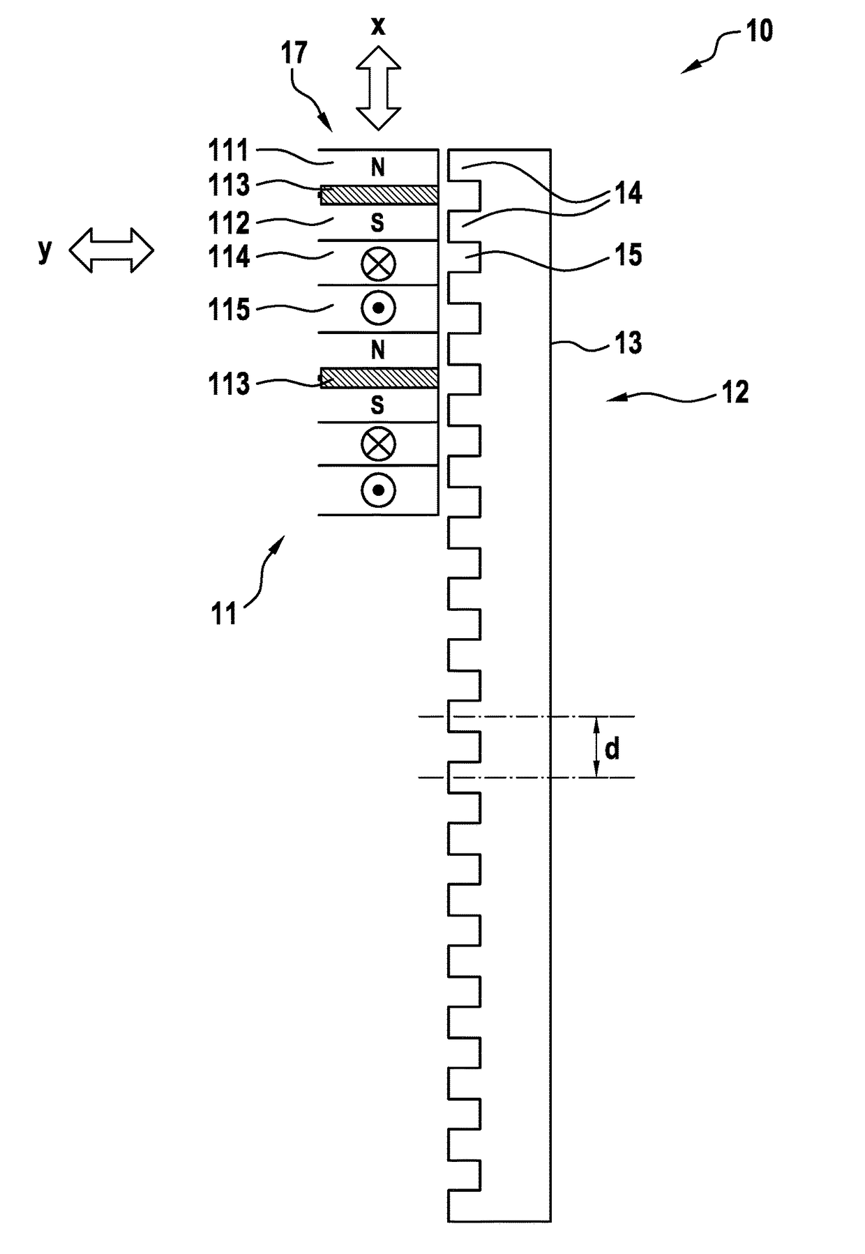
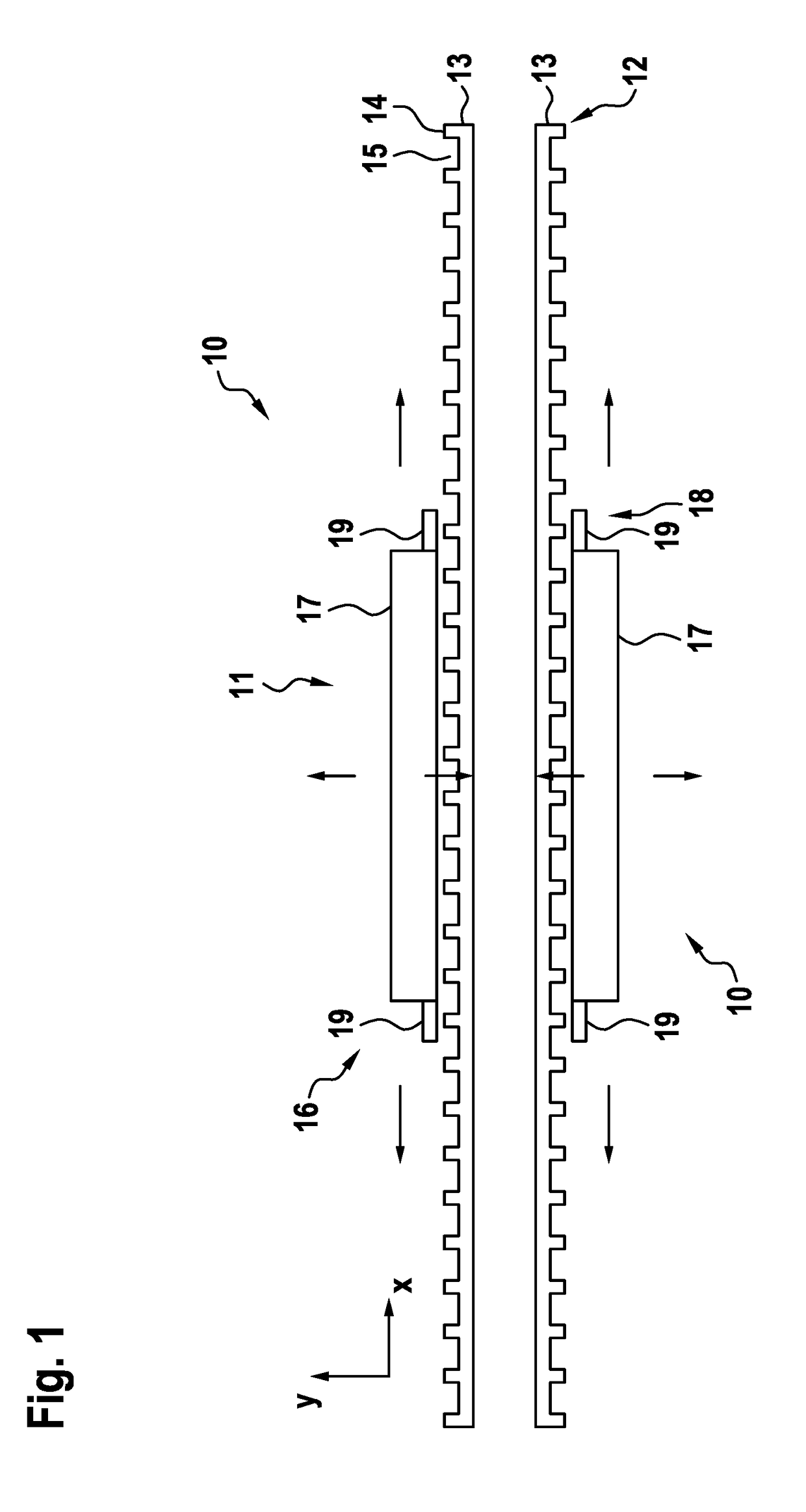
[0048]FIG. 1 shows a schematic side view of a linear motor 10 comprising a levitation unit and a sensing device of an exemplary embodiment of the present invention. A coordinate system x, y indicates a moving direction x and a levitation direction y which will be explained later. The linear motor 10 comprises a mover part 11 and a stator part 12. The stator part 12 comprises two stator rods 13 having first regions 14 exemplified as teeth or projections and second regions 15 exemplified as slots or indentations, alternating each other in the moving direction x which may also be understood as a longitudinal direction of the linear motor 10. The mover part 11 comprises a levitation unit 16 of two motor units 17. In the present embodiment, each motor unit 17 is exemplified as a flux switching permanent magnet linear motor (FSPMLM) unit function of which will be explained later in the context of FIG. 11. The motor units 17 are controllable or controlled by a control unit (not shown) to c...


PUM


Abstract

A method for levitation control of a linear motor includes supplying an alternating current or alternating voltage to at least one oscillating circuit including at least one sensing coil being or assumed to be arranged in a fixed spatial correlation to a mover part of the linear motor such that an opening plane of the sensing coil faces a sensor counter-surface of a stator part of the linear motor with a gap therebetween; receiving a response signal from the oscillating circuit; determining a gap length of the gap based on the response signal; and controlling the gap length by driving a magnetic levitation unit of the linear motor based on the determined gap length. An inductive sensing device and an elevator system, and a method for determining a position of the linear motor are also disclosed.

Description

[0001]The present invention relates to a method for levitation control of a linear motor, a method for measuring a position of a linear motor, an inductive sensing device, and an elevator system.BACKGROUND OF THE INVENTION[0002]A linear motor is known to be used to move cars of conveyors, trains, elevators, or the like. A linear motor comprises a stator part and a mover part. A stator part may comprise a toothed stator rail, and the mover part may comprise a number of motor units each having an arrangement of poles, permanent magnets, and electric coils controlled to generate a magnetic flux cooperating with the teeth of the stator rail, for generating a desired linear movement of the mover part with respect to the stator part. An air gap of a certain length is needed between the mover part and the stator rail for the linear motor to work properly. It is known to have pairs of motor units on opposite sides of the stator part, forming so-called levitation pairs (levitation units) kee...

Claims


Application Information

Patent Timeline
IPC IPC(8): H02N15/00H02K41/03H02P25/064B66B11/04
CPCH02N15/00B66B11/0407H02P25/064H02K41/033H02P6/16H02P6/17
Inventor PIITULAINEN, HENRYSUUR-ASKOLA, SEPPOPUROSTO, TERO
Owner KONE CORP
Why Eureka
Try Eureka