
System, method and computer program for operating a land- or marine-based multi-spool gas turbine

Active Publication Date: 2018-09-06
AURELIA TURBINES
View PDF0 Cites 49 Cited by
  • Summary
  • Abstract
  • Description
  • Claims
  • Application Information

AI Technical Summary

Benefits of technology

This patent describes a method and system for controlling the speed of the spokes in compressors to avoid surge conditions. The system uses electrical converters to determine the speed of the spokes and adjust the torque of the generators accordingly. This method and system have several technical advantages, including improved efficiency, faster control, and easier maintenance. It also eliminates the need for costly components with variable geometry mechanisms that are prone to wear and tear. Overall, this innovation offers a more effective and efficient solution for controlling the speed of compressors.

Problems solved by technology

At the same time as the electrical energy production is moving towards renewable energy based energy production, the electrical grid is also facing new challenges.
This centralized electrical power generation, of course, causes losses in the electrical grid because the energy must be transferred over long distances.
This is typically due to a lower electrical efficiency compared to large power plants.
In practice, typically, the low pressure turbine in a two-spool configuration will be choked over the most of the useful operating range.
Therefore, significant amounts of air need to be blown off after the low pressure compressor during the loading of the unit which is unbeneficial from the efficiency perspective.
This is due to the fact that at part-load conditions, there is less “back pressure” towards the compressors due to the lower amount of fuel combusted and smaller mass flow, therefore, operating the system closer to the surge conditions, which may cause one or both of the compressors to fail.
Therefore, it would be desirable to omit variable geometry mechanisms which are costly to manufacture, prone to wear and tear, and have high losses while posing threats to reliability.

Method used


Image

  • System, method and computer program for operating a land- or marine-based multi-spool gas turbine
  • System, method and computer program for operating a land- or marine-based multi-spool gas turbine
  • System, method and computer program for operating a land- or marine-based multi-spool gas turbine

Examples


Embodiment Construction

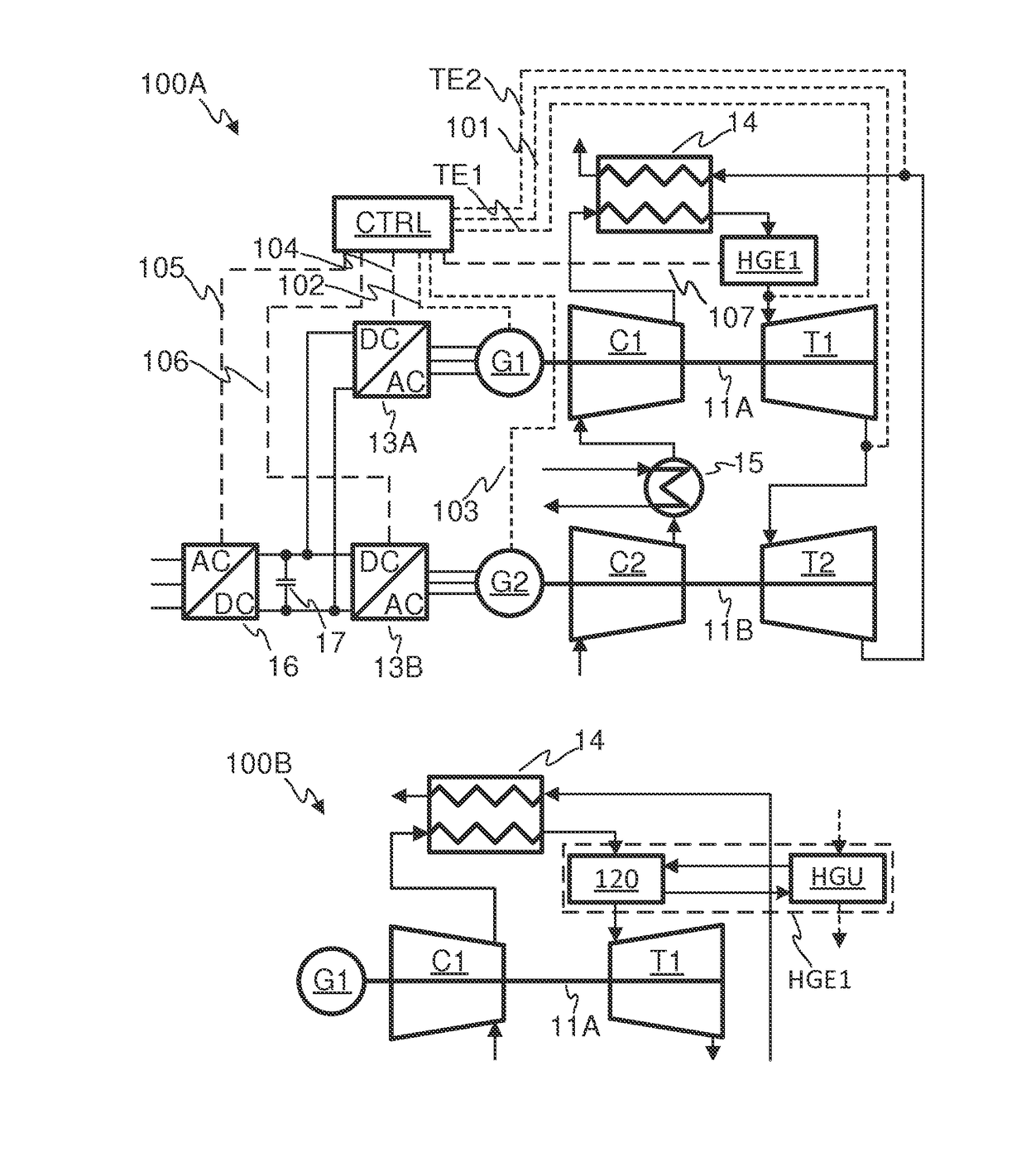
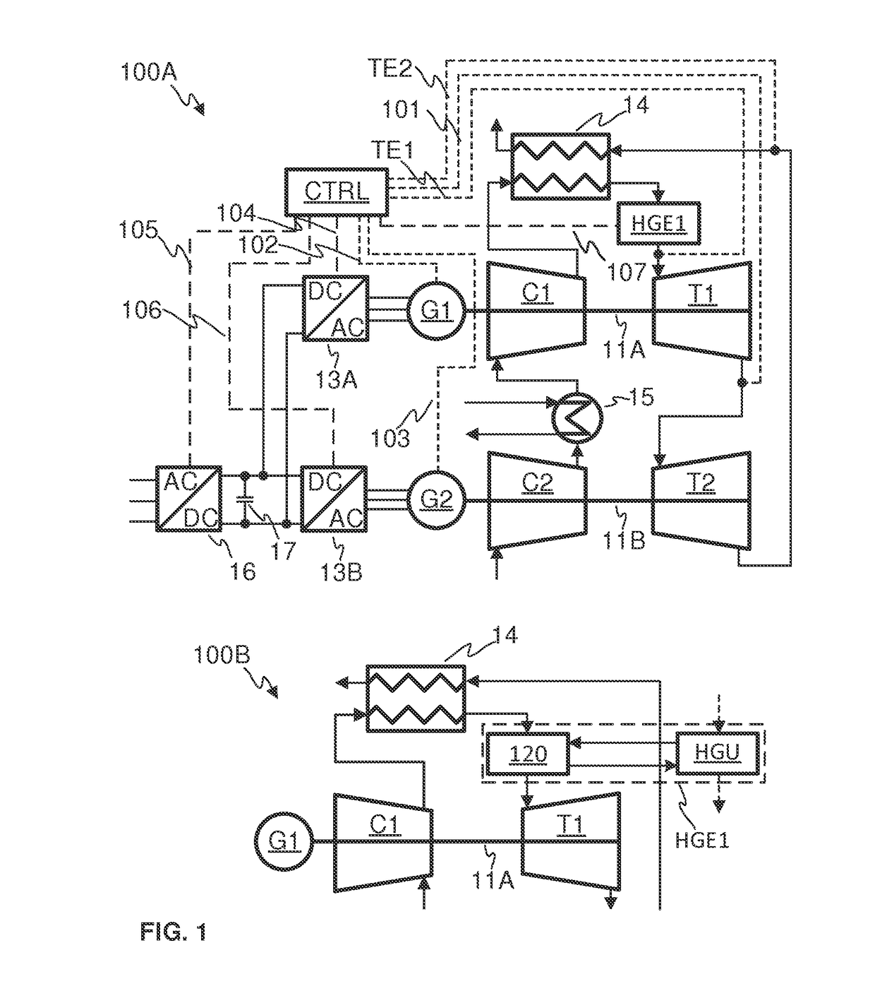
[0086]The present disclosure relates to a system for producing electrical power to supply a load by utilizing a land- or marine-based gas turbine and a method and a computer program for controlling thereof. Land-based gas turbines refer here to any stationary or moving application utilizing gas turbines on land. These may be, e.g., stationary power plants, trains, heavy duty-vehicles also known as heavy vehicles. Heavy vehicles may include, e.g., machinery utilized in earthwork operations.

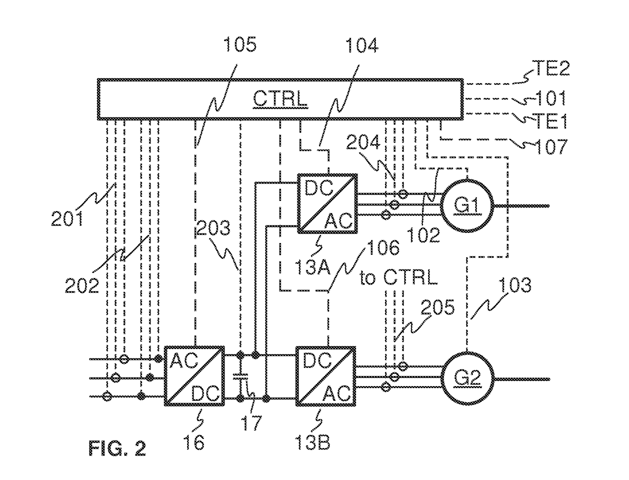
[0087]The system includes at least two spools each of which comprising at least a shaft and a turbine mounted on the shaft and at least one of the at least two spools further comprising a compressor. The system further comprises a first heat generating equipment and at least two generators, each one mounted on the predefined one of the shafts. The system may also comprise a first heat exchanger and / or at least one second heat exchanger and / or at least one second heat generating equipment.

[0088]The ...


PUM


Abstract

The present invention is a system, method and computer program for operating a land-or marine-based multi-spool gas turbine system for generating electrical power to supply a load, wherein the system comprises a multi-spool gas turbine engine, and the method comprises controlling the rotational speeds of the at least two generators independently of each other so as to directly control the rotational speeds of the shafts of the spools, the at last two generators being operable to generate electrical current to supply the load, and regulating the amount of heat generated the first heat generating equipment. A computer program to perform the method is also disclosed.

Description

TECHNICAL FIELD OF THE INVENTION[0001]The invention concerns in general the technical field of electrical and mechanical power generation by utilizing gas turbine plants. Especially the invention concerns the control of the operation of a land- or marine-based gas turbine plant with a multi-spool gas turbine for generating electrical power to supply a load.BACKGROUND OF THE INVENTION[0002]The electrical energy production is at the moment going through major changes. The pollution and greenhouse gas emissions of the energy sector have gained increasing attention. At the same time as the electrical energy production is moving towards renewable energy based energy production, the electrical grid is also facing new challenges. Previously, the power plants connected to the electrical grid were very large such as nuclear power plants, large coal-based power plants, etc. This centralized electrical power generation, of course, causes losses in the electrical grid because the energy must be...

Claims


Application Information

Patent Timeline
IPC IPC(8): F02C1/06F02C3/045F02C6/00F02C7/10
CPCF02C1/06F02C3/045F02C6/006F02C7/10F02C9/42H02K7/1815F05D2220/76F02C6/00F02C3/04F02C7/08H02K7/18
Inventor MALKAMÄKI, MATTIJAATINEN-VÄRRI, AHTIBACKMAN, JARIHONKATUKIA, JUHA
Owner AURELIA TURBINES
Learn More