Method and system for a first and a second supply of additive to an exhaust gas stream from an internal combustion engine

a technology of additive and exhaust gas, which is applied in the field of exhaust treatment system and computer program product for treating the exhaust stream, can solve the problems of increased back pressure, indirect impact on the cost of manufacture and/or production, and treatment system problems relating to inadequate soot oxidation in the filter, etc., to achieve the effect of reducing the amount of additiv

Active Publication Date: 2018-09-13
SCANIA CV AB
View PDF0 Cites 6 Cited by
  • Summary
  • Abstract
  • Description
  • Claims
  • Application Information

AI Technical Summary

Benefits of technology

[0031]The present invention provides, according to one embodiment, a control of a ratio NO2/NOx, between the amount of nitrogen dioxide NO2 and the amount of nitrogen oxides NOx in the exhaust stream, based on the future operating conditions. Thus, for example, too high values for this ratio may be avoided through the active control, wherein for example NO2/NOx>50% may be avoided, since the value for the ratio may be actively controlled to be reduced. The value for the ratio NO2/NOx may also be increased when the value is too low, for example if NO2/NOx<50%.
[0032]The present

Problems solved by technology

However, larger substrate volumes result in a direct impact on the cost of manufacture and/or production.
A larger substrate volume also results in a greater back pressure, which counteracts potential gains in fuel consumption, due to the higher conversion degree caused by the increased volume.
Prior art exhaust treatment systems often have problems relating to inadequate soot oxidation in the filter arranged in the system to catch and oxidize soot parti

Method used


Image

  • Method and system for a first and a second supply of additive to an exhaust gas stream from an internal combustion engine
  • Method and system for a first and a second supply of additive to an exhaust gas stream from an internal combustion engine
  • Method and system for a first and a second supply of additive to an exhaust gas stream from an internal combustion engine

Examples


Embodiment Construction

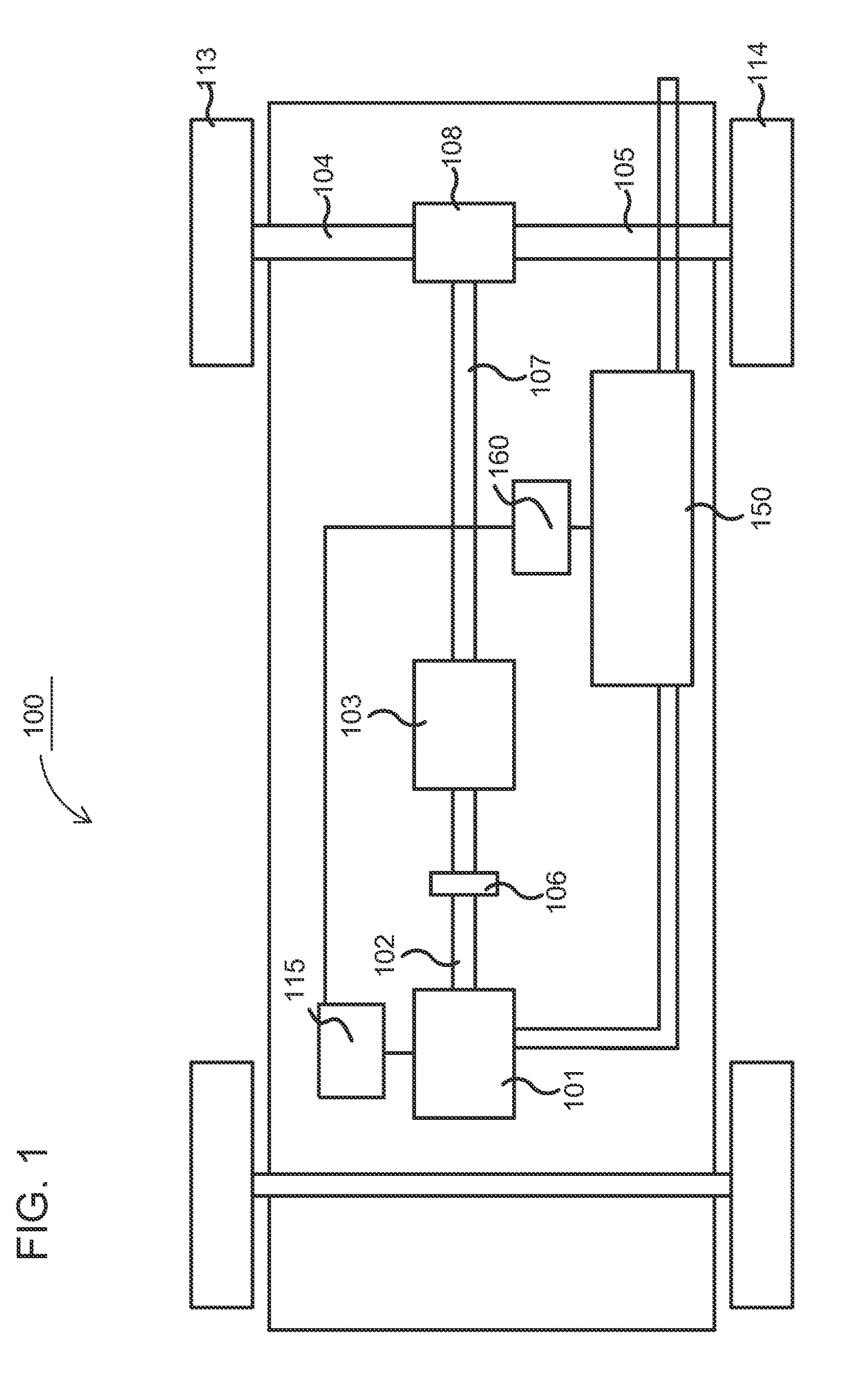
[0039]FIG. 1 schematically shows an example vehicle 100 comprising an exhaust treatment system 150, which may be an exhaust treatment system 150 according to one embodiment of the present invention. The power-train comprises a combustion engine 101, which in a customary manner, via an output shaft 102 on the combustion engine 101, usually via a flywheel, is connected to a gearbox 103 via a clutch 106.

[0040]The combustion engine 101 is controlled by the vehicle's control system via a control device 115. Likewise, the clutch 106 and the gearbox 103 may be controlled by the vehicle's control system, with the help of one or more applicable control devices (not shown). Naturally, the vehicle's power-train may also be of another type, such as a type with a conventional automatic gearbox, of a type with a hybrid power-train, etc.

[0041]An output shaft 107 from the gearbox 103 drives the wheels 113, 114 via a final drive 108, such as e.g. a customary differential, and the drive shafts 104, 1...


PUM


Abstract

Provided are a method and a system for treatment of an exhaust stream, from a combustion engine comprising nitrogen oxides. An estimate of at least one future operating condition for the exhaust treatment system is determined based on a road section ahead of the vehicle. A first additive is input into the exhaust stream to cause a first reduction of nitrogen oxides in a first reduction catalyst device. A second additive is input into the exhaust stream to cause a second reduction of a second amount of nitrogen oxides in a second reduction catalyst device, arranged downstream of the first reduction catalyst device. The first supply of additive is controlled based on the estimated at least one future operating condition, such that the first reduction catalyst device is exposed, over time, to a substoichiometric condition, with respect to the first additive and the first amount of nitrogen oxides.

Description

CROSS-REFERENCE TO RELATED APPLICATION(S)[0001]This application is a national stage application (filed under 35 § U.S.C. 371) of PCT / SE2016 / 050794, filed Aug. 25, 2016 of the same title, which, in turn claims priority to Swedish Application No. 1551111-6, filed Aug. 27, 2015 of the same title; the contents of each of which are hereby incorporated by reference.FIELD OF THE INVENTION[0002]The present invention relates to a method, an exhaust treatment system, and a computer program product for treatment of an exhaust stream.BACKGROUND OF THE INVENTION[0003]The following background description constitutes a description of the background to the present invention, and thus need not necessarily constitute prior art.[0004]In connection with increased government interests concerning pollution and air quality, primarily in urban areas, emission standards and regulations regarding emissions from combustion engines have been drafted in many jurisdictions.[0005]Such emission standards often con...

Claims


Application Information

Patent Timeline
IPC IPC(8): F01N3/20F01N3/035F01N13/00F01N3/10
CPCF01N3/206F01N2900/1621F01N13/0093F01N3/208F01N3/103F01N2560/026F01N2560/06F01N2560/14F01N2610/02F01N2900/08F01N2900/12F01N2900/1411F01N2900/1602F01N2900/1606F01N3/035F01N3/2066F01N9/00F01N2900/102F01N2900/1812G08G1/09623G08G1/09626G08G1/096716G08G1/096758G08G1/096775G08G1/096791Y02A50/20Y02T10/12Y02T10/40B60W50/0097
Inventor NILSSON
Owner SCANIA CV AB
Why Eureka
Try Eureka