Li-S Battery with Carbon Coated Separator

a technology of carbon coating and separator, which is applied in the direction of cell components, sustainable manufacturing/processing, and final product manufacturing, etc., can solve the problems of reducing the capacity of the battery, poor kinetics and low rate capability of the battery, and low porosity of the membrane with liquid electrolyte, so as to minimize capacity loss, reduce the migration of polysulphide intermediates, and reduce the effect of capacity loss

Active Publication Date: 2018-10-04
NORTH CAROLINA STATE UNIV +1
View PDF3 Cites 11 Cited by
  • Summary
  • Abstract
  • Description
  • Claims
  • Application Information

AI Technical Summary

Benefits of technology

[0012]The Li—S battery cell comprises a Sulphur-containing cathode, a Lithium-containing anode, a separator in between the cathode and anode with an electrolyte on both sides of the separator filling interspaces between the anode and the cathode. The separator contains electrically conducting carbon and prevents polysulphide intermediates from migrating from the Sulphur-containing cathode to the Lithium anode.
[0014]It is believed that the porosity of the separator influences the performance. As compared to a Celgard PP porous film, which is used in the above mentioned article by Yao, a fibrous separator with a higher porosity is regarded as superior.
[0015]Especially, with respect to glass fiber (GF) membranes, these not only have higher thermal stability and larger ionic conductivity but also possess superior electrochemical performance compared to microporous PP. GF membranes have excellent electrolyte wettability and are promising separator candidates for high-performance Li—S batteries.
[0018]However, for the fibrous substrate of the separator, also other types of nano-fibers are obtainable by electrospinning, centrifugal spinning or melt blowing. Examples include the following. Polyacrylonitrile (PAN), polyvinylidene fluoride (PVDF), polyvinylidene fluoride-co-hexafluoropropylene (PVDF-co-HFP), polyacrylonitrile / polyvinylpyrrolidone (PAN / PVP), polyamide (Nylon), or their blends. Nanopartides, for example, silicon dioxide (SiO2), titanium dioxide (TiO2), or graphene oxide (GO), can be introduced into electrospun nanofibers to form composite membranes to further increase the physical and electrochemical properties of separators.
[0022]It has been found that carbon layers with thickness far above 1 micron are advantageous, in contrast to the postulate of Yao et al. in the above-mentioned article, reading “the thickness (tens of microns) and the mass (several miligrams) of these interlayers are rather large, which if not reduced would substantially decrease the specific capacity of the cell”
[0031]In some embodiments, the Li—S battery cell comprises a fluid-tight enclosure with a bottom casing and a top casing, for example with an O-ring or other sealant that provides a fluid-tight sealing. Between the casings the cathode, the separator, and the anode are arranged in a sandwich configuration. Further, an elastic spring is arranged inside the enclosure which presses the sandwich configuration together for improving the electrical contact between the Sulphur cathode and the carbon layer of the separator.

Problems solved by technology

Once, the polysulphides reach the Li electrode, they get deposited and reduce the capacity of the battery.
It should be emphasized in relation to the Celgard PP separator of Yao et al. that, although, microporous polyolefin membranes are the most commonly-used separators for Lithium batteries due to their good chemical stability and mechanical strength, such membranes suffer from low porosity and poor wettability with liquid electrolyte.
The result is an increase of the cell resistance, resulting in poor kinetics and low rate capability of the batteries.
In addition, polyolefin-based separators exhibit large thermal shrinkage at high temperatures which may cause internal short circuits, fire and even explosions in case of overcharge or overheating
The aspects for improvements of Li—S batteries are complex, and the effects from the various components, including improved separator configuration, electrode materials, and electrolytes, as well as varying dimensions, are difficult to separate, which also makes direct comparison between various Li—S battery systems from different experimental designs difficult.

Method used


Image

  • Li-S Battery with Carbon Coated Separator
  • Li-S Battery with Carbon Coated Separator
  • Li-S Battery with Carbon Coated Separator

Examples


Embodiment Construction

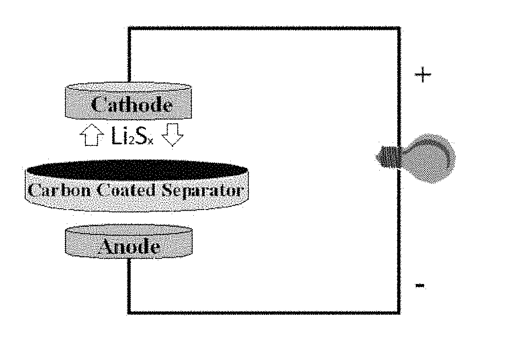
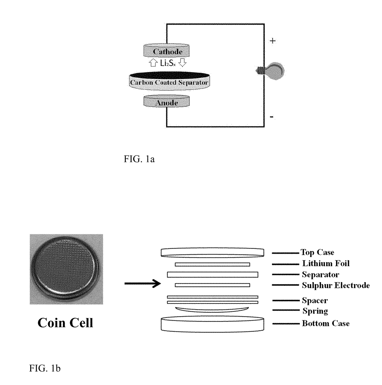
[0071]FIG. 1a illustrates the schematic configuration of a Li—S cell with carbon-coated separator. Offset is taken in a conventional Li—S battery design with a Sulphur cathode and a Lithium anode and a separator in between as well as an electrolyte (not shown). The separator comprises a carbon coating on its surface for preventing dissolved Li2Sx (4≤x≤8) in the electrolyte to reach the anode. This follows the approach as disclosed in the aforementioned article by Yao et al. The cathode comprises a Sulphur surface towards the separator, wherein the Sulphur surface is provided without a carbon coating

[0072]FIG. 1b contains a photograph of the battery cell that was constructed in experiments for which results are presented below. In the assembly sketch, it is seen that the battery cell comprises an enclosure with a bottom and top casing between which the battery components are arranged in addition to a spring that presses the Sulphur electrode, the separator and the Lithium foil togeth...


PUM

PropertyMeasurementUnit
thicknessaaaaaaaaaa
thicknessaaaaaaaaaa
diameteraaaaaaaaaa

Abstract

A Li—S battery cell comprising a Sulphur-containing cathode, a Lithium-containing anode, a separator in between the cathode and anode with an electrolyte on both sides of the separator filling interspaces between the anode and the cathode. The separator contains electrically conducting carbon and prevents polysulphide intermediates from migrating from the Sulphur-containing cathode to the Lithium anode.

Description

FIELD OF THE INVENTION[0001]The present invention relates to Li—S batteries with carbon coated separators between the electrodes.BACKGROUND OF THE INVENTION[0002]Due to their superior energy storage capacity in terms of Wh / kg (Watt*hour / kilogram) as compared to Lithium ion (Li-ion) batteries, efforts are targeting improvements of Lithium Sulphur (Li—S) batteries, especially with respect to improving the electrode capacity as well as improving the lifetime of the battery. The latter includes prevention or reduction of migration of polysulphide intermediates (Li2Sx, x=4, x=6, or x=8) through the electrolyte to the Li electrode. Polysulphides are intermediates created during the charging and discharging cycles. Once, the polysulphides reach the Li electrode, they get deposited and reduce the capacity of the battery.[0003]In some attempts for prevention of migration of polysulphides, carbon is provided on or in the Sulphur cathode. Examples include US2015 / 014890 and US2015 / 05607. Anothe...

Claims


Application Information

Patent Timeline
Patent Type & Authority Applications(United States)
IPC IPC(8): H01M2/16H01M10/052H01M4/38H01M2/02H01M10/0585H01M50/437H01M50/451H01M50/454
CPCH01M2/1666H01M10/052H01M4/382H01M2/166H01M2/1613H01M2/0222H01M10/0585Y02E60/10H01M50/44Y02P70/50H01M50/437H01M50/451H01M50/454H01M50/109H01M50/446
Inventor KIM, DAVIDZHANG, XIANGWUZHU, JIADENG
Owner NORTH CAROLINA STATE UNIV
Why Eureka
Try Eureka