
Microfluidic Model Of The Blood Brain Barrier

a brain barrier and microfluidic technology, applied in the field of brain cell culture, can solve problems such as neurovascular degeneration, achieve the effects of improving the maturation of astrocytes and bmecs, improving and maintaining barrier function, and enhancing endogenous media conditioning

Active Publication Date: 2018-10-18
EMULATE INC +1
View PDF2 Cites 4 Cited by
  • Summary
  • Abstract
  • Description
  • Claims
  • Application Information

AI Technical Summary

Benefits of technology

The invention is about culturing endothelial cells, astrocytes, and neurons in a microfluidic device that mimics the structure and function of the blood brain barrier and spinal cord. The microfluidic device allows for the measurement of barrier integrity and physiology through various testing measures, such as transepithelial electrical resistance and electrophysiology. The iPSC-derived neurons, particularly motor neurons, can be cultured in the microfluidic device for a relatively long time and exhibit more mature electrophysiology compared to static cultures. The microfluidic culture of cells helps to drive maturation and differentiation further than current systems.

Problems solved by technology

Not only because dysfunction of the blood-brain barrier leads to degeneration of the neurovascular unit, but also because drugs that are supposed to treat neurological disorders often fail to permeate the blood-brain barrier.

Method used


Image

  • Microfluidic Model Of The Blood Brain Barrier
  • Microfluidic Model Of The Blood Brain Barrier
  • Microfluidic Model Of The Blood Brain Barrier

Examples


example 1

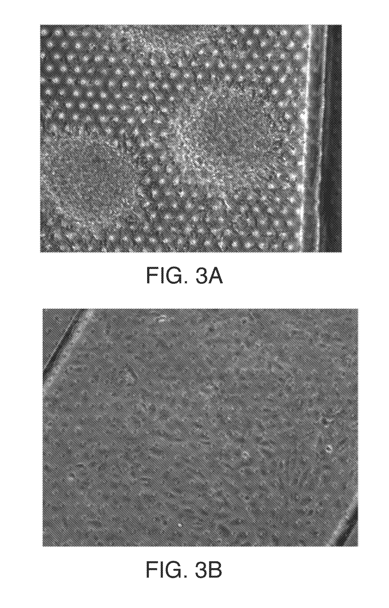
[0076]Cells are prepared either directly from cultured iPSCs or from frozen lots of pre-differentiated cells. Cells are thawed (or dissociated fresh) and seeded into the chip at day 8-9 (in the case of BMECs differentiation) and at various points in neural differentiation, In the case of MNs, for example, cells are seeded at day 12 of differentiation either from freshly differentiated cultures or directly from a thawed vial, iPSC-derived forebrain neural progenitor cultures (dubbed EZs) were cultured in chip either dissociated or as neural spheres that attached and extended in 3 dimensions (See FIG. 3A-B apical),The various factors used in the protocol (see above chart and tabs) for the generation of motor neurons are provided (using iPSCs as the starting material).

example 2

[0077]In this example, another protocol for the generation of motor neurons is provided using iPSCs as the starting material: The various factors used in the protocol per day (see FIG. 31) for the generation of motor neurons are provided (using iPSCs as the starting material).

example 3

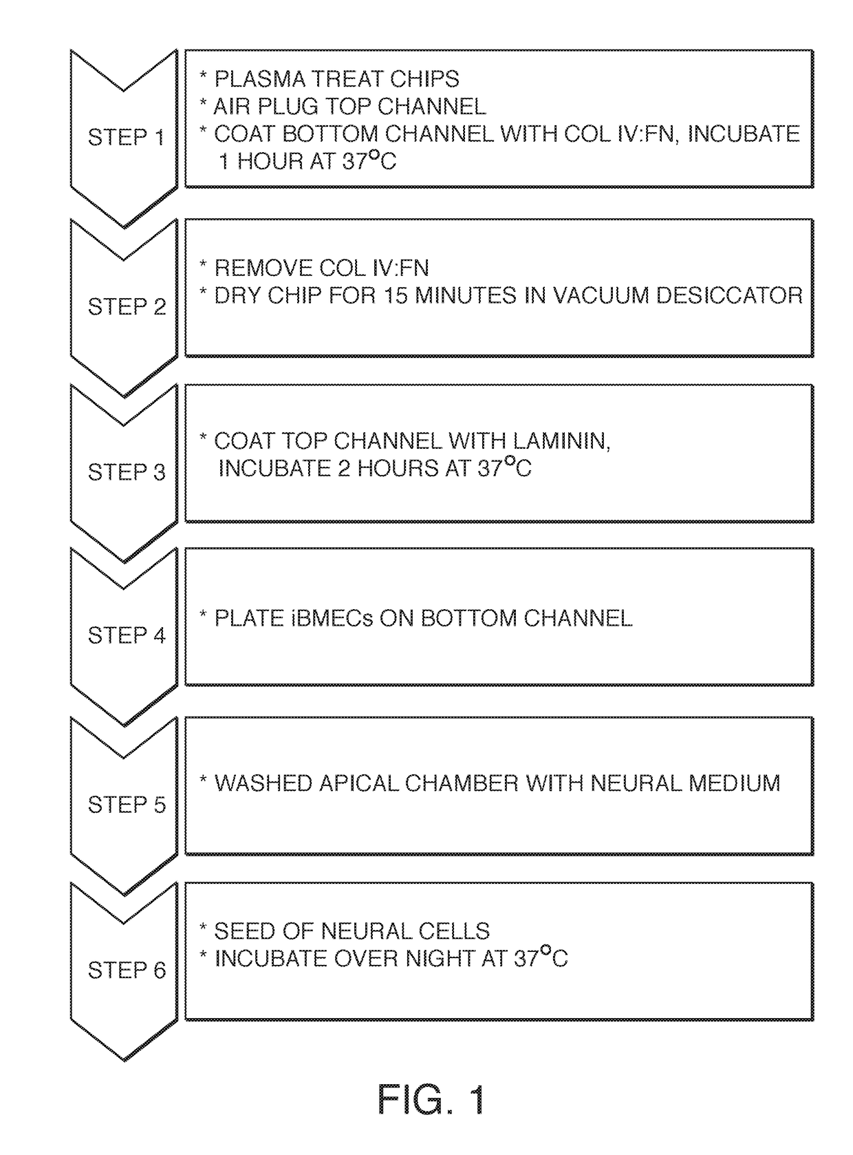
[0078]This example explores various conditions tested for seeding neural (EZ spheres and iMNPs) and endothelial cells (iBMECs) from frozen stocks of cells on surfaces treated with different extracellular matrices (ECMs). The best results for iBMECs were achieved with a mixture of collagen and fibronectin (4:1 ratio) using a seeding concentration of 5×10⁶ cells / ml (Table 1). Given these results, seeding was attempted on microfluidic devices, i.e. chips, Table 2 shows various conditions tested for seeding neural (EZ spheres, iNPCs and iMNPs) and endothelial cells (iBMECs) on the apical and basal sides of a microfluidic chip using frozen stocks of cells.

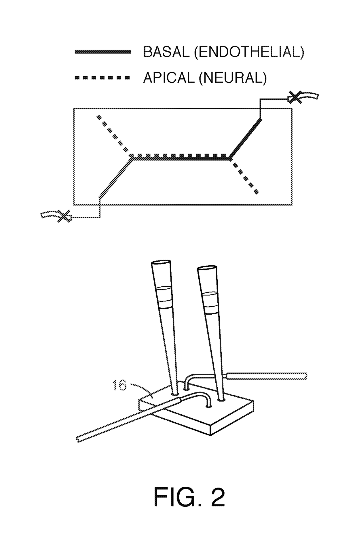
[0079]While a variety of protocols were explored, one embodiment for preparing and seeding a microfluidic chip comprising six steps. FIG. 1 shows the workflow, First, the chip (or regions thereof) are treated to promote wetting or protein adhesion (e.g. by plasma treatment). One or more channels are then plugged (see the top schematic o...


PUM


Abstract

The invention relates to culturing brain endothelial cells, and optionally astrocytes and neurons in a fluidic device under conditions whereby the cells mimic the structure and function of the blood brain barrier. Culture of such cells in a microfluidic device, whether alone or in combination with other cells, drives maturation and / or differentiation further than existing systems.

Description

FIELD OF THE INVENTION[0001]The invention relates to culturing brain cells and particularly astrocytes together with endothelial cells in a fluidic device under conditions whereby the cells mimic the structure and function of the blood brain barrier and / or spinal cord. Good viability and function allow for measurements of barrier integrity and physiology, whether by trans-epithelial electrical resistance (TEER), patch clamp or other testing measures.BACKGROUND OF THE INVENTION[0002]The blood-brain barrier is of major clinical relevance. Not only because dysfunction of the blood-brain barrier leads to degeneration of the neurovascular unit, but also because drugs that are supposed to treat neurological disorders often fail to permeate the blood-brain barrier. Because of its importance in disease and medical treatment, it would be highly advantageous to have a predictive model of the human blood-brain barrier that recapitulates aspects of the cerebral endothelial microenvironment in a...

Claims


Application Information

Patent Timeline
IPC IPC(8): C12N5/0793C12Q1/02C12N5/071C12N5/079C12M3/06C12M1/12C12M1/42
CPCC12N5/0619C12Q1/02C12N5/0692C12N5/0622C12M23/16C12M25/02C12M35/08C12N2502/28C12N2502/081C12N2502/086C12N2535/10C12N2533/52C12N2533/54C12N2533/56C12N5/0618C12N5/069C12N2506/45C12N2531/00C12N2539/00B01L3/502761B01L2200/0647B01L2300/0861B01L3/5027
Inventor KERNS, S. JORDANWEN, NORMANLUCCHESI, CAROLINAHINOJOSA, CHRISTOPHER DAVIDFRASER, JACOBHAMILTON, GERALDINEVATINE, GADSANCES, SAMUELSVENDSEN, CLIVELEVNER, DANIELSAREEN, DHRUV
Owner EMULATE INC
Learn More