

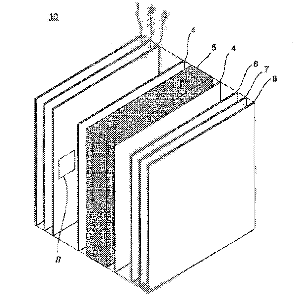
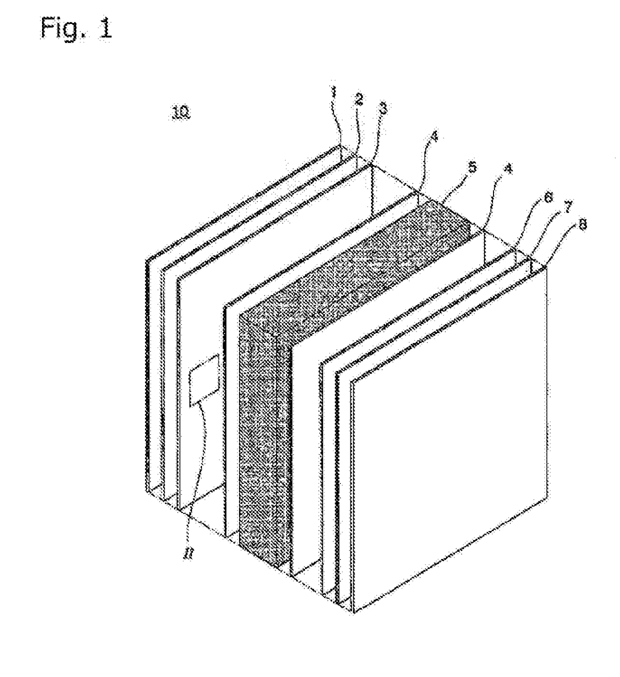
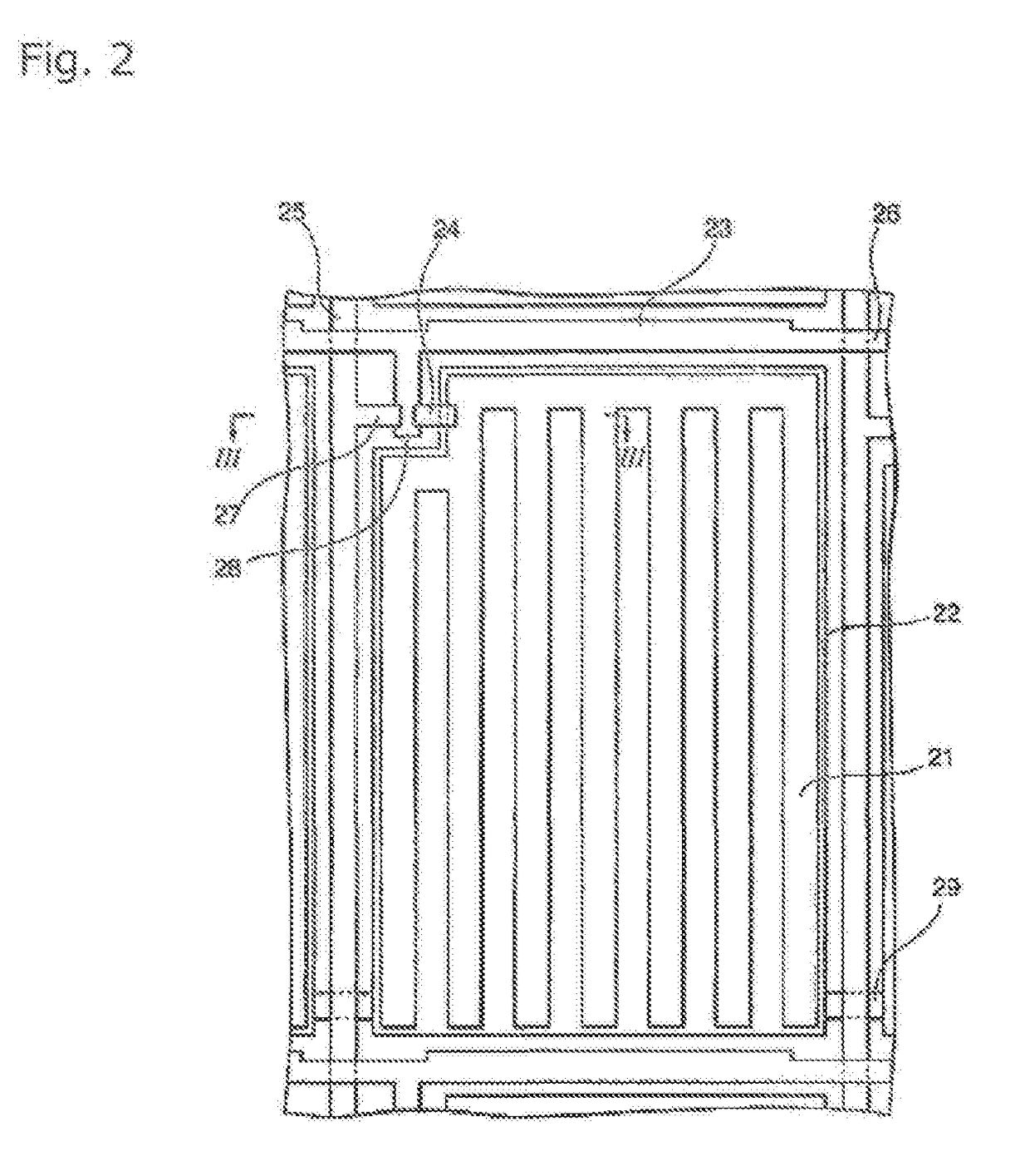
Liquid crystal display element
a display element and liquid crystal technology, applied in the field of liquid crystal display elements, can solve the problems of not being suitable for practical use, the voltage of the element is more than 80, and the halftone display necessary for full-color display is not easily obtained, so as to achieve efficient production, improve the decay time of the liquid crystal, and high sensitivity
- Summary
- Abstract
- Description
- Claims
- Application Information
AI Technical Summary
Benefits of technology
Problems solved by technology
Method used
Image

Examples
example 1
[0301]A composition 1 was prepared by mixing 97% of an N-type liquid crystal composition (LCN-1), 2.94% of a polymerizable compound (V1), and 0.06% of a photopolymerization initiator No. 1 shown in Table 10 below (3% of a polymerizable composition as a mixture of the polymerizable compound and the photopolymerization initiator).
[0302]A polyimide alignment film was formed on glass substrates, and the glass substrates was subjected to rubbing alignment treatment such that the pretilt angle was 1° to 2° with respect to the direction normal to the substrates in order to obtain vertical liquid crystal alignment (homeotropic alignment), and a rubbing alignment cell with ITO and having a cell gap of 3 μm was produced.
[0303]The composition 1 was heated to 60° C. to dissolve the polymerizable compound (V1) in solid form. A polarizing microscope was used to confirm that the polymerizable compound (V1) was uniformly dissolved in a nematic liquid crystal phase in the composition 1 at room tempe...
examples 37 to 39
[0326]VA-mode liquid crystal display elements were produced in the same manner as in Example 1 except that a liquid crystal composition, a polymerizable compound, and an initiator shown in Table 6 below were used.
[0327]Each of the produced cells was placed between two orthogonal polarizing plates. Under a polarizing microscope, a dark image was observed. The level of blackness of the dark image did not change even when the cell was rotated in an azimuth angle direction, and the cell was found to have homeotropic alignment. It was therefore confirmed that the optical axis direction of the polymer network was the same as the easy alignment axis direction of the liquid crystal composition.
[0328]Each of the compositions used to produce the cells was left to stand at 20° C. for 1 week, and it was confirmed that no crystallization of the polymerizable compound occurred.
[0329]A rectangular wave of 60 Hz was applied to each of the obtained VA mode liquid crystal display elements to measure ...
examples 40 and 41
[0330]VA-mode liquid crystal display elements were produced in the same manner as in Example 1 except that a liquid crystal composition, a polymerizable compound, and an initiator shown in Table 7 below were used.
[0331]Each of the produced cells was placed between two orthogonal polarizing plates. Under a polarizing microscope, a dark image was observed. The level of blackness of the dark image did not change even when the cell was rotated in an azimuth angle direction, and the cell was found to have homeotropic alignment. It was therefore confirmed that the optical axis direction of the polymer network was the same as the easy alignment axis direction of the liquid crystal composition.
[0332]Each of the compositions used to produce the cells was left to stand at 20° C. for 1 week, and it was confirmed that no crystallization of the polymerizable compound occurred.
[0333]A rectangular wave of 60 Hz was applied to each of the obtained VA mode liquid crystal display elements to measure ...
PUM
| Property | Measurement | Unit |
|---|---|---|
| absorption wavelength | aaaaa | aaaaa |
| pretilt angle | aaaaa | aaaaa |
| temperature | aaaaa | aaaaa |
Abstract
Description
Claims
Application Information