Heat-dissipating plate for high-power element

a technology of heat dissipation plate and high-power element, which is applied in the direction of cooling/ventilation/heating modification, lighting and heating apparatus, and modification by conduction heat transfer, etc. it can solve the problems of low thermal expansion coefficient, defects in the elements, and difficulty in application of composite materials such as several-hundred watt-level transistors. , to achieve the effect of high thermal conductivity and low thermal expansion coefficien

Inactive Publication Date: 2018-11-15
THE GOODSYST
View PDF10 Cites 5 Cited by
  • Summary
  • Abstract
  • Description
  • Claims
  • Application Information

AI Technical Summary

Benefits of technology

[0009]A heat-dissipating plate according to the present invention can achieve a low thermal expansion coefficient in the plane direction of the plate of 9×10⁻⁶ / K or less, while also attaining a high thermal conductivity in the thickness direction of the plate of at least 300 W / mK, and in the case of a more exemplary embodiment, at least 350 W / mK, and thus may be appropriately used as a heat-dissipating plate in a high-power semiconductor element requiring joining with a ceramic material, such as alumina, having a low thermal expansion coefficient.

Problems solved by technology

However, since the thermal conductivity of such composite materials is at most about 250 W / mK, high conductivities of 300 W / mK or higher required by several-hundred Watt-level power transistors are unable to be achieved, and thus the composite materials are limited in that application in elements such as several-hundred Watt-level transistor is difficult.
Moreover, brazing processes for joining with ceramic materials such as alumina (Al2O3) are essential in processes for manufacturing semiconductor elements, and since such brazing joining processes take place at high temperatures of at least 800° C., warping or damage occurs during the brazing joining process due to the difference in thermal expansion coefficient between the metal composite substrate and the ceramic material.
Thus, there is also a limitation wherein the occurrence of such warping and damage causes defects in the elements.

Method used


Image

  • Heat-dissipating plate for high-power element
  • Heat-dissipating plate for high-power element
  • Heat-dissipating plate for high-power element

Examples


example 2

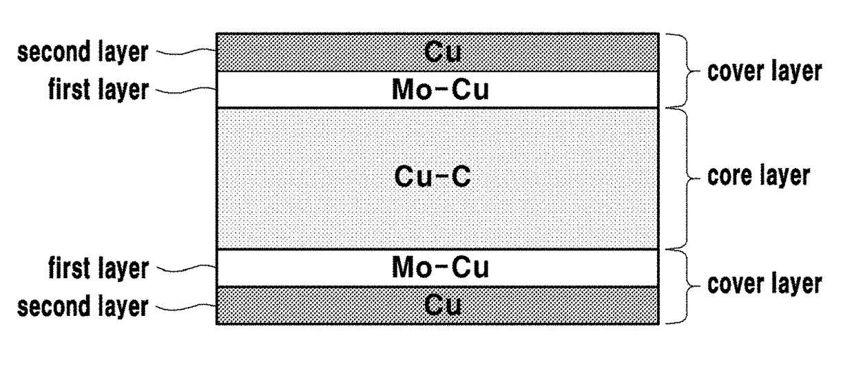
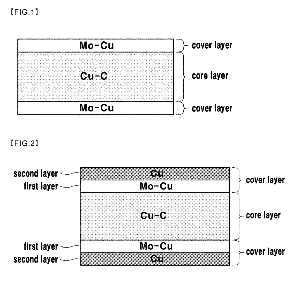
[0055]A plate-shaped first layer, in which a 100-150 μm thick Cu plate is stacked, was formed in a mold.

[0056]Also, a plate-shaped second layer, in which a 50-100 μm thick Mo—Cu (64 wt % Mo-36 wt % Cu) is stacked, was formed on the first layer.

[0057]Also, in forming the third layer composed of Cu and a graphite phase, the third layer was formed by using a plate shape in which a Cu-plated graphite powder was manufactured by the same method as in Example 1 of the invention.

[0058]Also, a plate-shaped fourth layer, in which a 50-100 μm thick Mo—Cu (64 wt % Mo-36 wt % Cu) is stacked, was formed on the third layer.

[0059]Also, a plate-shaped fifth layer, in which a 100-150 μm thick Cu plate is stacked, was formed on the fourth layer.

[0060]In Example 2 of the present invention, Mo—Cu plates or Cu plates were used by being laminated, but the first layer, second layer, fourth layer, and fifth layer may also be formed by compression molding Mo—Cu or Cu powder.

[0061]By repeating the lamination ...

example 3

[0064]Processes other than the sintering process were performed identically to Example 2 of the present invention, and a metal-based composite plate was obtained by performing a sintering process of the core material at a sintering temperature of 900° C., an applied pressure of 80 MPa, and a sintering time of 20 minutes.

example 4

[0065]Processes other than the sintering process were performed identically to Example 2 of the present invention, and a metal-based composite plate was obtained by performing a sintering process of the core material at a sintering temperature of 850° C., an applied pressure of 80 MPa, and a sintering time of 20 minutes.

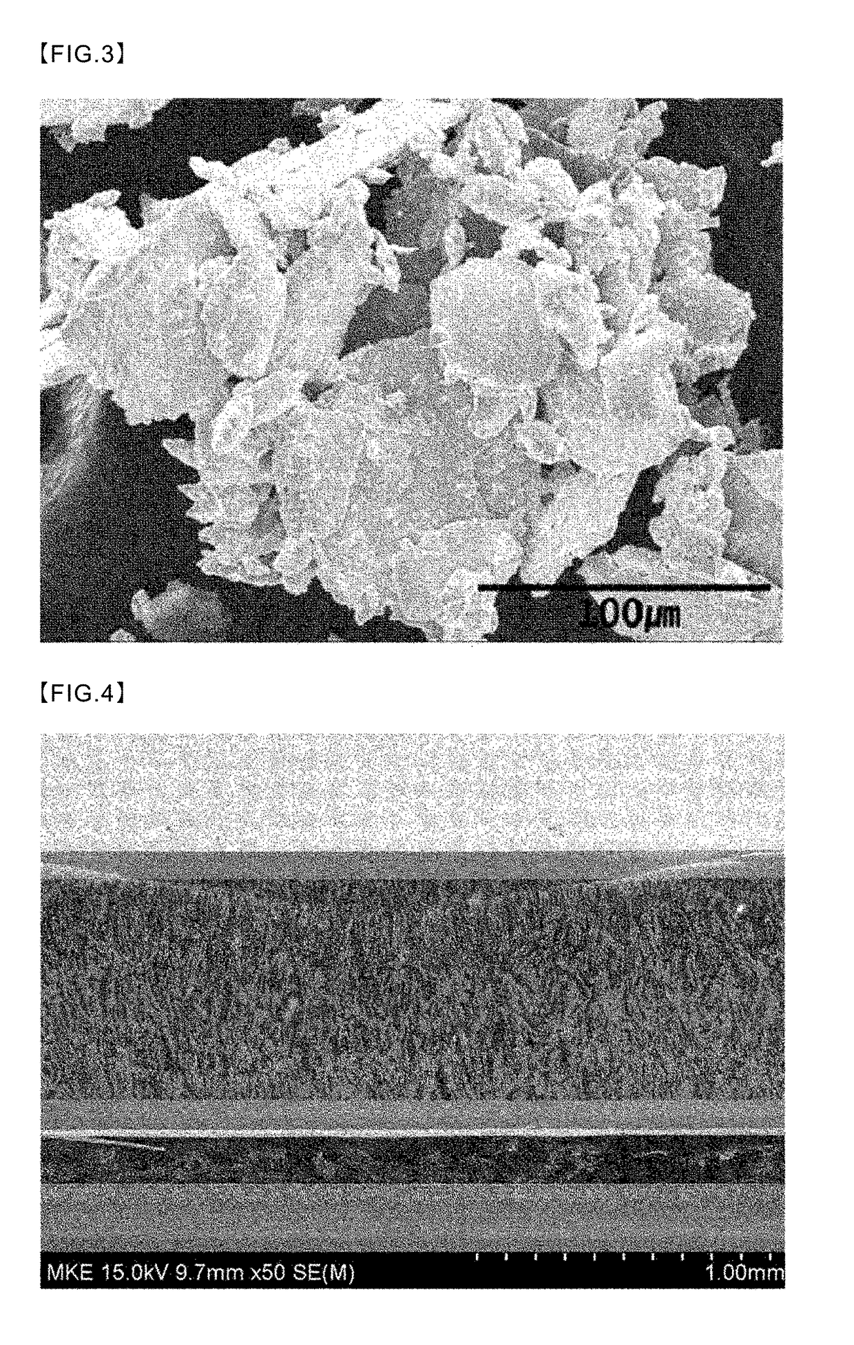
[0066]FIG. 4 is a scanning electron micrograph of a thickness direction cross section of a heat-dissipating plate manufactured according to Example 1 of the present invention.

[0067]As illustrated in FIG. 4, a cover layer (the light grey part of the figure) absent a graphite particle phase and composed of a Mo—Cu alloy is formed to a depth of about 100 μm from the surface of the top face and bottom face of a heat-dissipating plate manufactured according to Example 1 of the present invention, and in the middle, a composite phase in which graphite particles are distributed in a Cu matrix is formed to a thickness of about 1 mm. Moreover, FIG. 5 is an image of a Cu-graphi...


PUM

PropertyMeasurementUnit
thicknessaaaaaaaaaa
thicknessaaaaaaaaaa
temperaturesaaaaaaaaaa

Abstract

A heat-dissipating plate comprises a core layer; and two cover layers formed by being laminated on the top and bottom face of the core layer, wherein, the core layer is composed of a composite material in which a carbon phase is composited in a Cu matrix, the cover layer is composed of a Mo—Cu alloy, and the thermal conductivity in the thickness direction of the heat-dissipating plate is at least 300 W/mK, and the thermal expansion coefficient of the heat-dissipating plate in a direction perpendicular to the thickness direction is at most 9×10⁻⁶/K.

Description

TECHNICAL FIELD[0001]The present invention relates to a heat-dissipating plate, and more particularly, to a heat-dissipating plate which may be suitably used in packaging for a high-power semiconductor element using a compound semiconductor, wherein the heat-dissipating plate has the same or a similar heat expansion coefficient as a ceramic material, such as alumina, to enable a satisfactory joint to be established even when joined with the ceramic material, and at the same time, can attain a high thermal conductivity capable of quickly discharging to the outside, large quantities of heat generated from the high-power semiconductor element.BACKGROUND ART[0002]Recently, high-power amplifying elements using GaN-type compound semiconductors are receiving attention as a core technology in the fields of information and communications, and national defense.[0003]Such high-power electronic elements or optical elements generate large quantities of heat compared to general elements, and pack...

Claims


Application Information

Patent Timeline
Patent Type & Authority Applications(United States)
IPC IPC(8): F28F21/02H05K7/20F28F21/08
CPCF28F21/02H05K7/2039F28F21/085F28F21/089H01L23/3735H01L23/3736H05K7/209
Inventor KIM, IL-HOCHO, MEOUNG-WHANKIM, YOUNG-SUK
Owner THE GOODSYST
Why Eureka
Try Eureka