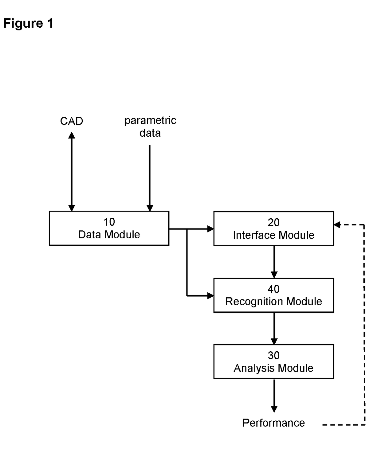
The result can be inaccurate predictions of product performance.
Not all the methods are possible at the start.
Typically, only relatively simple analyses are possible when the product definition is light, and it is only towards the end of the
design process that more complex analyses are possible.
Often, these different levels of fidelity require different CAE packages, with all the problems of data transfer, data updates within the
design process etc.
In addition, a model suitable for mathematical analysis for one performance measure will not be suitable for another.
In addition, there is a risk that the user will use a detailed analysis when the information describing the rotating machine assembly (input data) merits only a simple analysis; this may lead to errors in the analysis, yet the user may not know.
Furthermore, because the models are created manually, and in different applications, a change in the information describing the rotating machine assembly (product definition) does not, and often cannot, get cascaded to other analyses run in different applications.
Yet this aspect of performance is typically dealt with by a completely different computer programme, CAD (
Computer Aided Design), which has little or no calculation capability to predict other aspects of product performance, and poor or non-existent links to the analysis packages that do.
The result is a disconnect in the design process, poor productivity, sub-optimal products and wasted economic activity.
There is a further problem with complex analyses.
However, once an analysis becomes highly complex, it is possible that the result will be too complex to be understood or that it does not match the engineers' fundamental understanding of its performance.
Thus, the tension exists—there is a desire to increase complexity since this is assumed to increase accuracy and product performance, yet take this too far and complex analysis ceases to be of use.
Analysing a larger
system with all of the system influences tends to lead towards a more complex analysis, yet as has been discussed this leads to problems with speed of modelling and analysis and in
data interpretation.
For many years, data had to be transferred between these two definitions manually, which is slow, error-prone and problematic for the rapid design-analysis-redesign iterations required for the design of modern products.
However, for housings,
planet carriers and differential cages, they are non-axi-symmetric and thus standardised parametric definitions and simple analytical models do not exist.
Navigating this process is cumbersome with the consequence that it cannot be attempted in the concept
design stage, when rapid design-analysis-redesign iterations are required, and even when the design has settled down in the detailed
design stage, it hinders design optimisation.
The result is that gearbox design is hindered and product quality suffers.
If such FE models are included, the analysis results may be more accurate but the potential for design changes is severely limited since it would mean embarking on more model importing / exporting.
If the designer wishes to retain freedom to modify the design, there is a risk that the analysis results may be inaccurate to the extent that the gearbox design created is not fit for purpose.
Within the practical time constraints of a realistic design project, this process continually fails to provide insight to the engineer, who is left to approximate, hope, and / or continue with risk to the project and / or a sub-optimal gearbox design.
This poor integration of CAD and CAE and poor availability of accurate mathematical models to guide the design process has a particular manifestation in the design of planetary gear (or epicyclic) systems.
The properties of the
planet carrier have a substantial influence on the static deflections, durability and dynamic properties of the driveline containing the planetary gear, however, until the end of the design process this data is not available.
Where the structural model of a motor is to be included in the driveline system, the same issue occurs.
One problem with Timoshenko beam models is that the decision on what shaft steps to include and exclude is down to the engineer creating the model.
This is computationally expensive, but more importantly it may be inaccurate since, as the
aspect ratio of a Timoshenko beam becomes higher (bigger
diameter to length ratio), the accuracy decreases.
Thus, a more detailed definition of the form may be less accurate.
As has been described before, once the engineer decides to make this change in model construction the potential for gearbox
design modification is substantially reduced, and this change in modelling approach is not reversible since you cannot obtain a 1D (Timoshenko beam) model from a 3D Finite Element definition of the shaft.
Due to the nature of topology, any arbitrary 3D volume can be filled with a mesh of tet elements, whereas a hex mesh suffers from continuity problems.
While this works in principal, the practice means that solution times become very much longer.
There is a lack of standardisation, and results for the same
analytical problem differ depending on the judgment and experience of the engineer carrying out the work.
The problem is that this mesh needs to be sufficiently precise for the most precise calculation for which it might be used, meaning that it is excessively precise for all the other calculations.
This can slow down
data processing times for the analyses where a lower level of precision is sufficient.
The limitation of this is that the shell elements may not be appropriate for all parts of the shaft, and manual intervention is needed to define and manage the transition between shell and 3D finite elements, a procedure which is slow and open to interpretation, judgment and variability.
However, these functions exist in generalist packages, which have no specialist guidance or processes for the analysis of driveline systems.
In addition to being comparatively inaccurate and slow for analysis, these meshes have additional limitations with regard to the analysis of drivelines.
It is possible to see hex based meshes for driveline shafts in published literature, however they are predominantly for hollow shafts, since packages struggle to maintain mesh continuity through to the centre of
solid shafts.
This calculation is slow in FE and the iteration is not guaranteed to converge on a stable solution.
It also impacts upon the operating misalignment of the gears, which affects gear durability,
noise and efficiency.
The problem with this approach is that the raceway is assumed to be a rigid ring.
There are limitations in the accuracy of the calculation of the loadsharing among the rolling elements and hence life of the bearing.
An out of round raceway leads to a modified
stress field within the housing which changes the housing durability, and hence omission of this influence is an inaccuracy.
The problem with dynamic analysis is that Finite Element models of the housing are rarely accurate above 5 kHz, which leaves large areas of the audible spectrum vulnerable to inaccurate analysis.
These localized and small geometrical features are quite sensitive to manufacturing errors.
This is the reason why FE models are not accurate at high frequencies.
The way that the simulations are set up is open to interpretation, thus
quality control is a problem.
There is a temptation to add complexity to a
simulation just in case it is needed, with the belief that the more complex it is the more accurate the result.
This leads to the following problems.
The modelling process is slow since the
simulation takes a long time to set up.
Such complexity requires an expert user to be able to set up the simulation, which is expensive and may lead to
resource constraints.
Making the simulation more complex, which is always a temptation with increasing computer power and more sophisticated
software, makes both of these outcomes more likely.
Complex simulations have another
disadvantage, in that some of the data required to get the result is not available until near the end of the design process.
All of these have other ways of being simulated and, again, there is the danger that simulations will be set up in different packages (for example, Computational Fluid Dynamics for efficiency, Multi-domain simulation packages for gear shift control, Multi-
Body Dynamics for driveability) by different departments or companies.
The process of data update when a design change is made is slow and error-prone, and as the number of different simulation tools increases, this problem becomes worse.
An engineer cannot efficiently assess the
impact of a design change.
The whole design process of design and simulation becomes slow compared to the need for rapid product development.
However, such geometry was normally exported in the form of “dumb” geometry, such as STEP or IGES, which cannot be used for the parametric modelling which is a
standard function of modern CAD packages.
In this, the STEP or IGES definition of a component can be directly manipulated and dimensions changed, although the model of the resulting component is dumb and transfer back to a Parametric definition is not possible.
The problem with this is that the precise shape of the root is required if generalist analysis packages such as Finite
Element Analysis is to be used to calculate the root stress.
In the absence of such data, the gear designer estimates the shape of the root and the analyst ends up with an incorrect stress value.
The problem with the parametric definition of gears is that these data need to be transferred to the CAD definition, which ends up being a process of transcription.

