Additively manufactured casting core-shell hybrid mold and ceramic shell

a technology of additive manufacturing and ceramic shell, which is applied in the field of additive manufacturing of casting core-shell hybrid mold and ceramic shell, can solve the problems of increasing the complexity of internal cooling passages of turbine components, increasing the importance and difficulty of effective cooling of turbine blades, and increasing the need for more complicated and intricate internal geometries. , to achieve the effect of reducing the build time of the core and shell, improving the structural integrity of the mold, and reducing the amount of materials required

Active Publication Date: 2019-01-03
GENERAL ELECTRIC CO
View PDF12 Cites 8 Cited by
  • Summary
  • Abstract
  • Description
  • Claims
  • Application Information

AI Technical Summary

Benefits of technology

[0015]The core-shell mold may be fabricated through the use of additive manufacturing techniques. More specifically the method may comprise making a ceramic mold having a core and shell. The method having steps of (a) contacting a cured portion of a workpiece with a liquid ceramic photopolymer; (b) irradiating a portion of the liquid ceramic photopolymer adjacent to the cured portion through a window contacting the liquid ceramic photopolymer; (c) removing the workpiece from the uncured liquid ceramic photopolymer; and (d) repeating steps (a)-(c) until a ceramic mold is formed. After step (d), the process may further include a step (e) of pouring a liquid metal into a casting mold and solidifying the liquid metal to form the cast component. After step (e), the process may further include a step (f) comprising removing the mold from the cast component, and this step preferably involves a combination of mechanical force and chemical leaching in an alkaline bath. By adding a second ceramic material on at least a portion of the ceramic mold in step (d), at least one of the following advantages can be achieved: improvement of the structural integrity of the mold; reduction in build time of the core and shell; reduction in materials required to form the mold; ability to tailor the material properties of the mold; ability to tailor the thermal properties of the mold; and / or improvement in casting efficiency and / or production.

Problems solved by technology

Accordingly, in combination with manufacturing components of the turbine (e.g. turbine blades and stator vanes) from a high-temperature resistant material, effective cooling of the turbine blades, stator vanes and other components have become increasingly important and challenging.
The desire for increased cooling efficiency within turbine engine has led to complex internal cooling passages within turbine components.
However, these post-casting modifications are limited and given the ever increasing complexity of turbine engines and the recognized efficiency improvements provided by certain cooling circuits inside turbine blades, more complicated and intricate internal geometries are required.
While investment casting is capable of manufacturing these parts, positional precision and intricate internal geometries become more complex to manufacture using these conventional manufacturing processes and thus increase manufacturing time and expense significantly.
The ceramic core-shell molds according to the '151 patent are significantly limited by the printing resolution capabilities of these processes.
However, the available printing resolution of these systems significantly limits the ability to make filaments of sufficiently small size to serve as effective cooling holes in the cast final product.
Staggered vertical cavities are necessitated by the fact that the powder bed and SLA techniques disclosed in the '151 patent require vertically supported ceramic structures and the techniques are incapable of reliably producing filaments.
This resolution is simply not available in a powder bed process.
Similarly, stereolithography is limited in its ability to produce such filaments due to lack of support and resolution problems associated with laser scattering.
Although powder bed and SLA may be used to produce filaments, their ability to produce sufficiently fine filaments as discussed above is limited.
Further, in employing the above-mentioned DLP method of manufacturing a core-shell of the embodiment described above, various difficulties arise in integrating the use of a core-shell mold into an efficient manufacturing process.
For example, the time required to form a core-shell mold having sufficient dimensional stability (e.g., wall thickness) using a DLP process may delay the manufacturing process and require the use of excess material.

Method used


Image

  • Additively manufactured casting core-shell hybrid mold and ceramic shell
  • Additively manufactured casting core-shell hybrid mold and ceramic shell
  • Additively manufactured casting core-shell hybrid mold and ceramic shell

Examples


Embodiment Construction

[0050]While the aspects described herein have been described in conjunction with the example aspects outlined above, various alternatives, modifications, variations, improvements, and / or substantial equivalents, whether known or that are or may be presently unforeseen, may become apparent to those having at least ordinary skill in the art. Accordingly, the example aspects, as set forth above, are intended to be illustrative, not limiting. Various changes may be made without departing from the spirit and scope of the disclosure. Therefore, the disclosure is intended to embrace all known or later-developed alternatives, modifications, variations, improvements, and / or substantial equivalents.

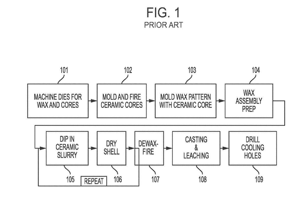
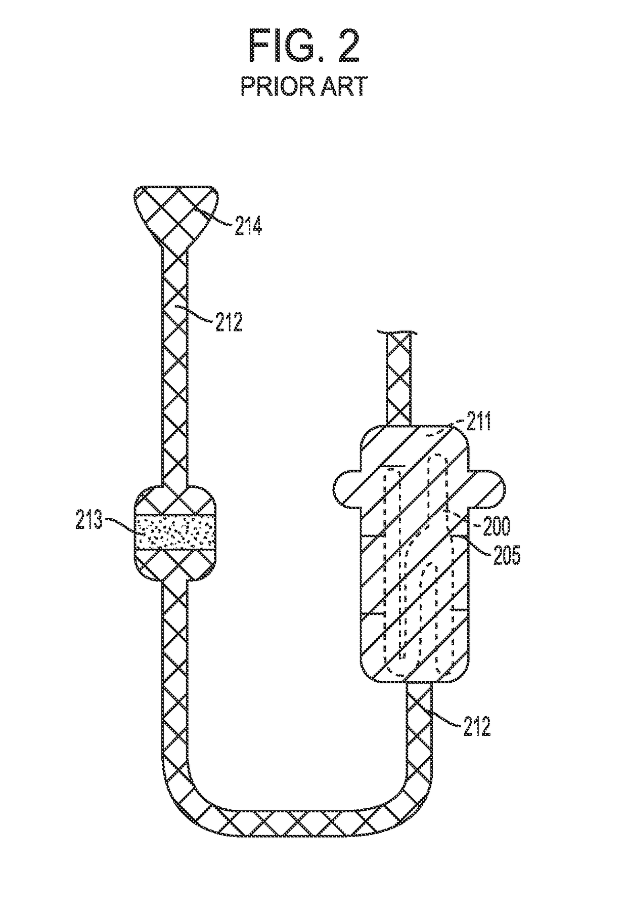
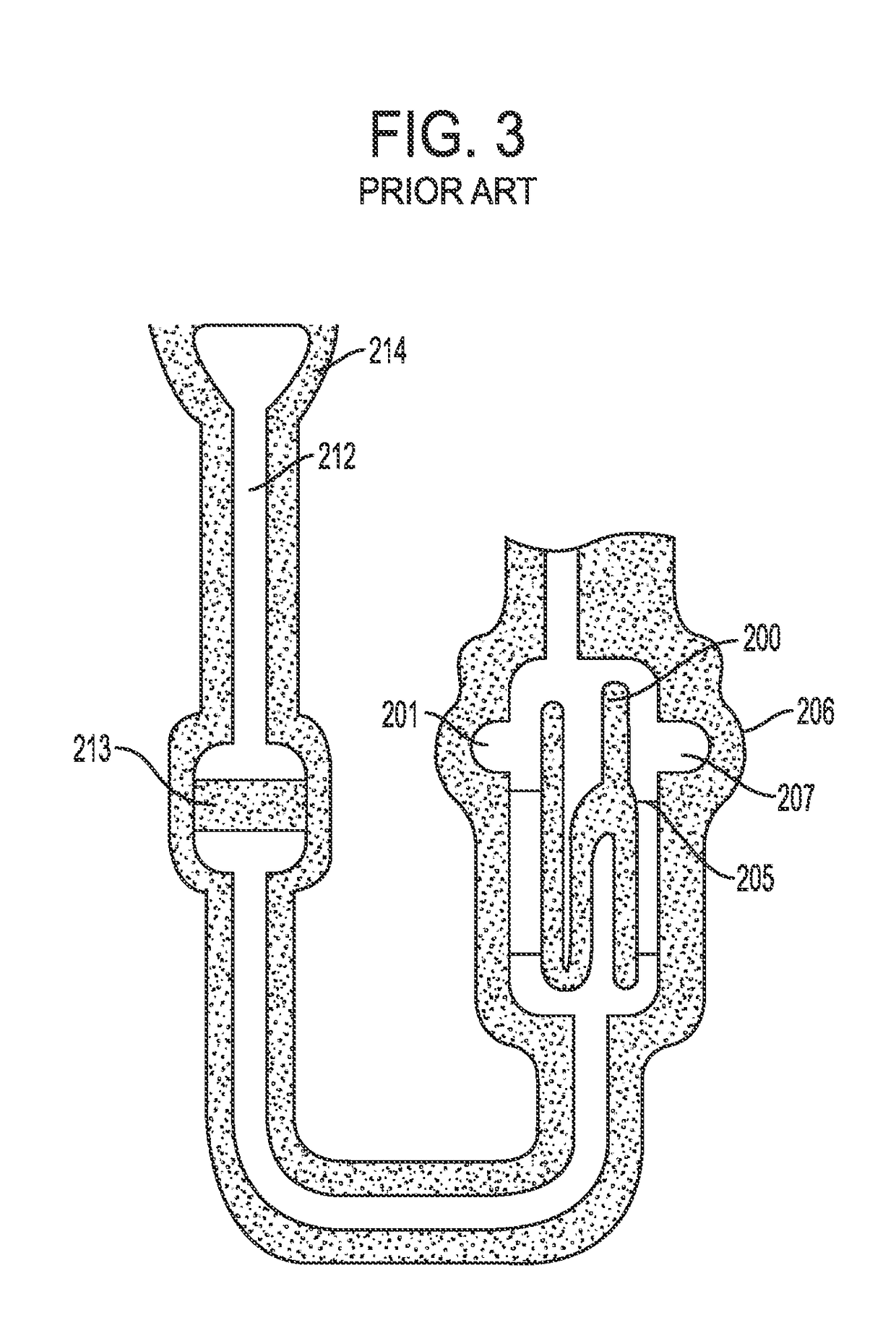
[0051]For example, the present invention provides a preferred method for making cast metal parts, and preferably those cast metal parts used in the manufacture of jet aircraft engines. Specifically, the production of single crystal, nickel-based superalloy cast parts such as turbine blades, vanes, ...


PUM

PropertyMeasurementUnit
diameteraaaaaaaaaa
cross sectional areaaaaaaaaaaa
areaaaaaaaaaaa

Abstract

The present disclosure generally relates to integrated core-shell investment casting molds that provide a filament structure corresponding to a cooling hole pattern in the surface of the turbine blade, stator vane, or shroud. The disclosure also relates to the forming of a ceramic coating on at least a portion of the shell of the core-shell casting mold.

Description

INTRODUCTION[0001]The disclosure generally relates to investment casting core-shell mold components and processes utilizing these components. The core-shell mold made in accordance with the present invention includes integrated ceramic filaments between the core and shell of the mold that can be utilized to form passages and / or holes in the cast component made from these molds. The integrated core-shell molds provide useful properties in casting operations, such as in the casting of superalloys used to make turbine blades and stator vanes for jet aircraft engines or power generation turbine components. The disclosure also relates to the coating of an integrated core-shell mold with a ceramic outer layer, which may provide any one or combination of the following exemplary benefits: to increase structural integrity of the core-shell mold; to bond or connect portions of the mold; to provide passageways or cavities in fluid communication with the mold; to control structural properties o...

Claims


Application Information

Patent Timeline
Patent Type & Authority Applications(United States)
IPC IPC(8): B22C9/10B28B1/00B22C9/04B22D29/00B33Y10/00B33Y80/00
CPCB22C9/10B28B1/001B33Y80/00B22D29/002B33Y10/00B22C9/04B22C9/22B28B11/045Y02P10/25
Inventor YANG, XICOLE, MICHAELBROWN, MICHAELGARAY, GREGORY TERRENCEPANG, TINGFANPRZESLAWSKI, BRIAN DAVIDKONITZER, DOUGLAS GERARD
Owner GENERAL ELECTRIC CO
Why Eureka
Try Eureka