
Transistor element with gate electrode of reduced height and raised drain and source regions and method of fabricating the same

a technology of gate electrode and source region, which is applied in the field of transistor elements with gate electrodes of reduced height and raised drain and source regions, can solve the problems of affecting the switching speed of respective transistor elements, and increasing the thickness of gate dielectric materials, so as to reduce the height of respective complex gate electrode structures, reduce the overall conductivity of gate electrode structures, and high degree of compatibility

Inactive Publication Date: 2019-02-07
GLOBALFOUNDRIES INC
View PDF7 Cites 5 Cited by
  • Summary
  • Abstract
  • Description
  • Claims
  • Application Information

AI Technical Summary

Benefits of technology

The present disclosure is about a method to improve the performance of semiconductor devices by reducing the height of complex gate electrode structures. This is achieved by forming a highly conductive metal-containing electrode material in an early manufacturing stage, which helps to maintain overall conductivity while reducing gate length dimensions. This method also helps to reduce parasitic capacitance between the gate electrode structure and adjacent drain and source regions, which can improve device performance. Additionally, this method simplifies the manufacturing process and reduces the risk of overlay errors and margin issues.

Problems solved by technology

Since the supply voltage may not be reduced to extremely low values, a further reduction of the thickness of the gate dielectric material, when composed of standard dielectric materials, such as silicon dioxide, silicon nitride and the like, may become increasingly problematic due to the over-proportional increase of respective leakage currents.
Although high capacitive coupling between the gate electrode and the channel region is basically a necessity for the required channel controllability, in particular, for ever-decreasing channel lengths, other capacitances involved in a field effect transistor are typically considered as parasitic capacitances, since these mostly undesirable capacitances may negatively affect the switching speed of respective transistor elements.
For example, the drain / gate and the source / gate capacitance may contribute to a reduced switching speed and, thus, to significant dynamic losses, particularly when operating the respective field effect transistors on the basis of moderately high clock frequencies.
On the other hand, significant additional process steps may be required for implementation of the three-dimensional configuration, thereby significantly adding to the overall production costs of such sophisticated semiconductor devices.
In particular, upon further reducing the critical dimensions of the transistor elements, the patterning sequence for forming the contact openings, in particular, the contact openings for the drain and source regions, becomes increasingly challenging since respective overlay errors may result in undesired shorting of the drain and / or source region with the gate electrode structure when a respective contact opening exposes, due to an overlay error, not only a part of the drain or source region, but also a part of the adjacent gate electrode material.
Consequently, the formation of the contact elements for connecting to the drain and source regions may result in significant yield loss.
Moreover, it turns out that overall resistance of the gate electrode structures formed in accordance with the process techniques described above, as well as the resulting parasitic capacitance between the gate electrode structure and the raised drain and source regions, may have a significant negative influence on the transistor performance, in particular, on further reduced transistor length dimensions.
For addressing some of the above-identified problems, sophisticated manufacturing techniques have been developed in which the gate electrode structures may be formed in a very late manufacturing stage by replacing a dummy gate electrode structure, thereby, however, contributing to overall increased process complexity and rendering these approaches less than desirable for many sophisticated semiconductor products.

Method used


Image

  • Transistor element with gate electrode of reduced height and raised drain and source regions and method of fabricating the same
  • Transistor element with gate electrode of reduced height and raised drain and source regions and method of fabricating the same
  • Transistor element with gate electrode of reduced height and raised drain and source regions and method of fabricating the same

Examples


Embodiment Construction

[0037]In the following description, for the purposes of explanation, numerous specific details are set forth in order to provide a thorough understanding of exemplary embodiments. It should be apparent, however, that exemplary embodiments may be practiced without these specific details or with an equivalent arrangement. In other instances, well-known structures and devices are shown in block diagram form in order to avoid unnecessarily obscuring exemplary embodiments. In addition, unless otherwise indicated, all numbers expressing quantities, ratios and numerical properties of ingredients, reaction conditions and so forth used in the specification and claims are to be understood as being modified in all instances by the term “about.”

[0038]Various illustrative embodiments of the invention are described below. In the interest of clarity, not all features of an actual implementation are described in this specification. It will of course be appreciated that in the development of any suc...


PUM


Abstract

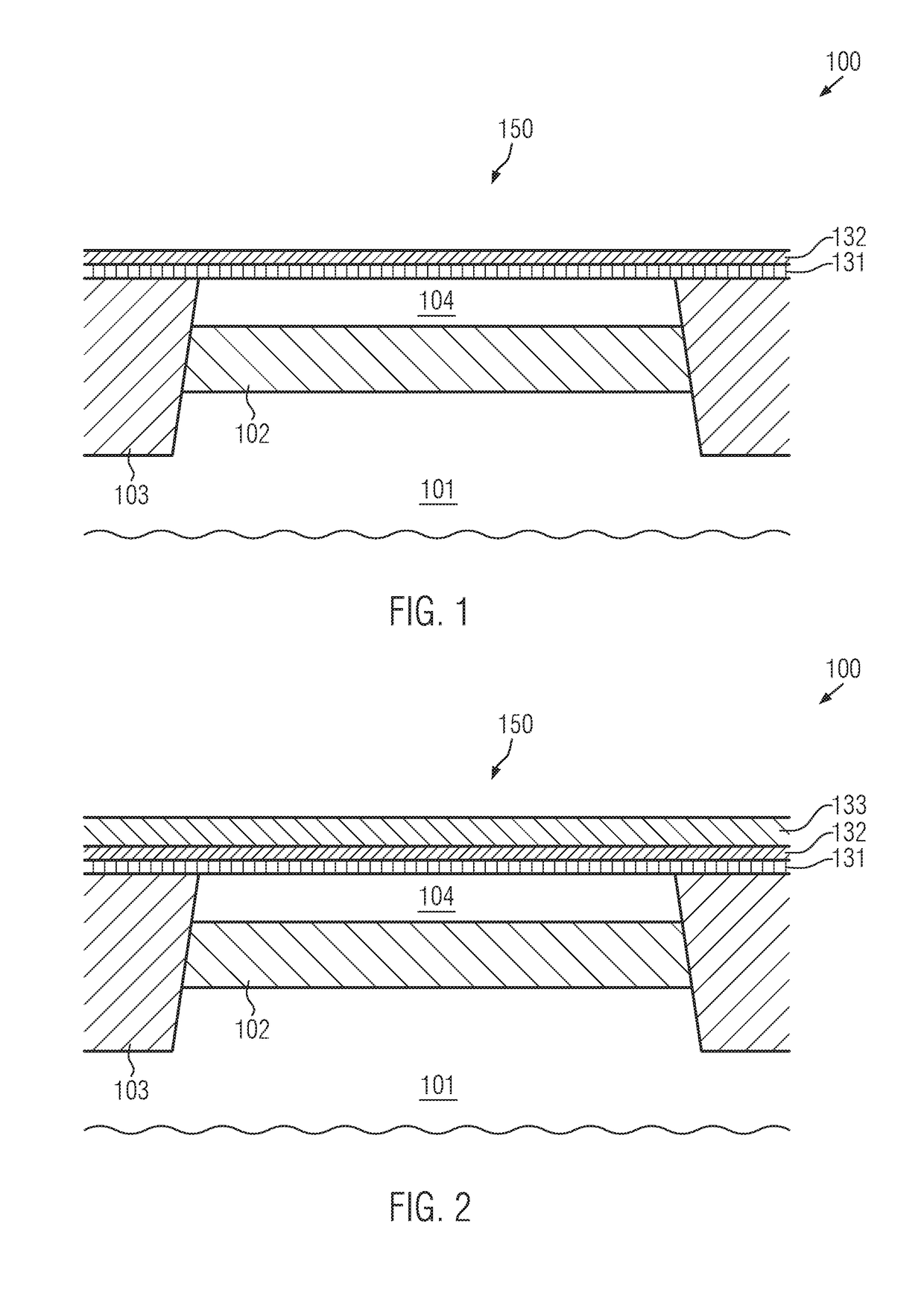
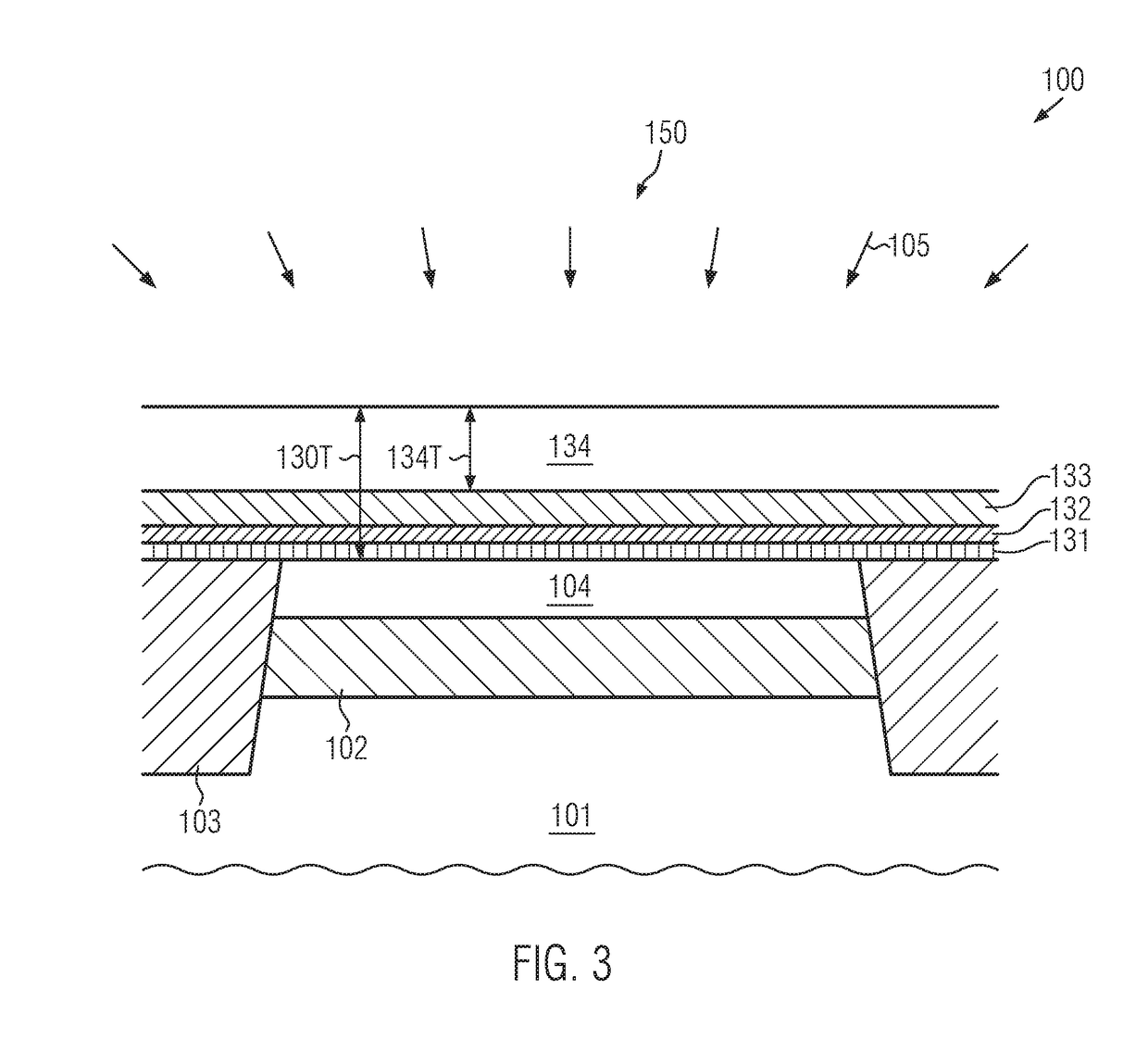
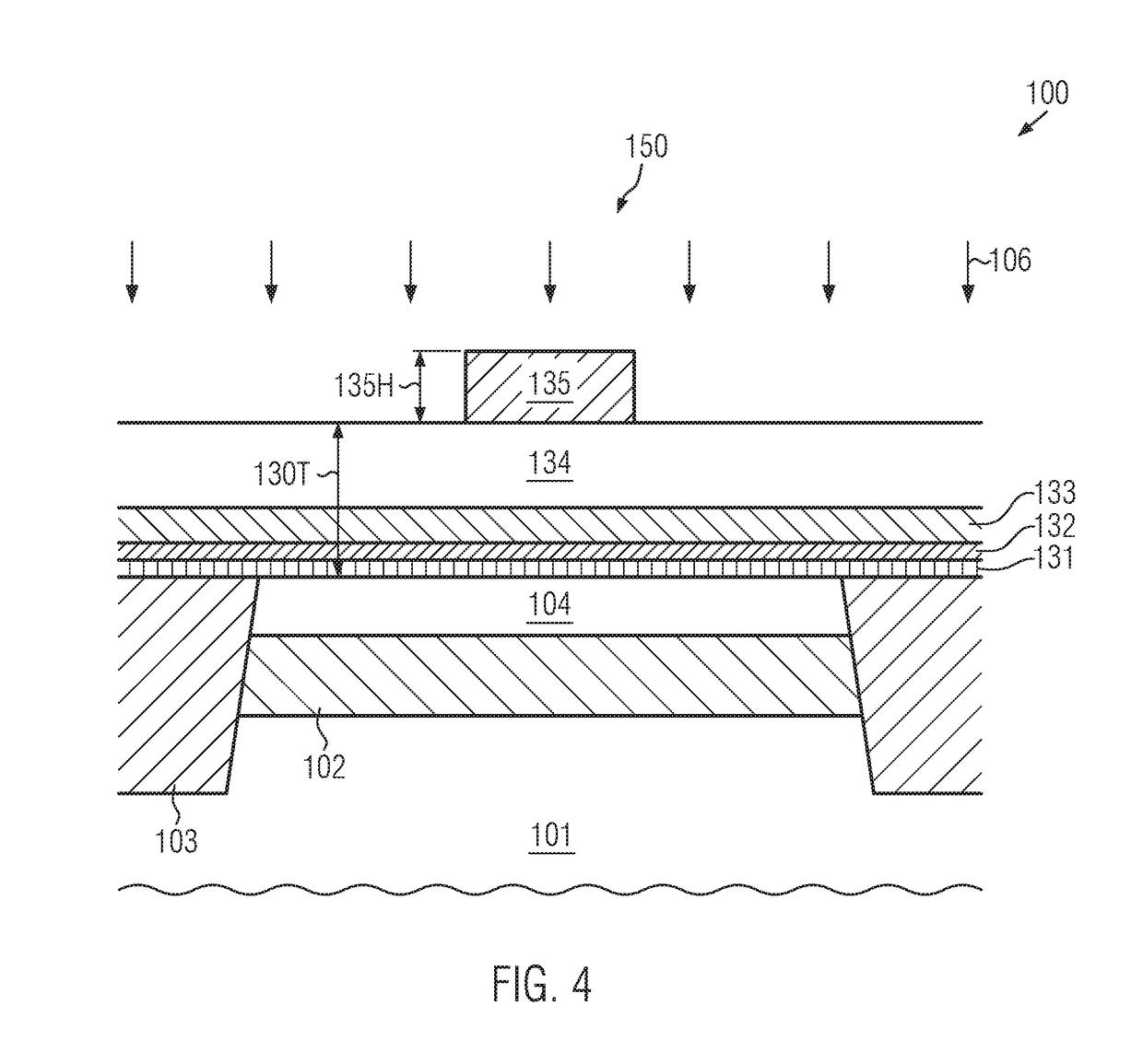
A transistor element of a sophisticated semiconductor device includes a gate electrode structure including a metal-containing electrode material instead of the conventionally used highly doped semiconductor material. The metal-containing electrode material may be formed in an early manufacturing stage, thereby reducing overall complexity of patterning the gate electrode structure in approaches in which the gate electrode structure is formed prior to the formation of the drain and source regions. Due to the metal-containing electrode material, high conductivity at reduced parasitic capacitance may be achieved, thereby rendering the techniques of the present disclosure as highly suitable for further device scaling.

Description

BACKGROUND1. Field of the Disclosure[0001]Generally, the present disclosure relates to transistor elements of semiconductor devices and respective manufacturing techniques, and, more particularly, to a transistor element with a gate electrode of reduced height and raised drain and source regions and a method of fabricating the same.2. Description of the Related Art[0002]Significant progress has been made in the field of semiconductor devices, when considering overall integration density, power consumption, switching speed and the like. Sophisticated integrated circuits up to and beyond several millions of field effect transistors may be typically implemented in complex control circuitry, thereby providing the potential of integrating increasingly additional functions into a single semiconductor chip. In recent developments, even entire electronic systems have been integrated into a single chip, wherein, in particular, frequently, radio frequency (RF) circuit portions may have to be ...

Claims


Application Information

Patent Timeline
Patent Type & Authority Applications(United States)
IPC IPC(8): H01L29/66H01L29/417
CPCH01L29/41783H01L29/66575H01L29/513H01L29/517H01L29/665H01L29/66545H01L29/66628H01L29/78654H01L29/4908H01L29/41733H01L21/84H01L21/76897
Inventor BAARS, PETERTHEES, HANS-JUERGENFITZ, CLEMENS
Owner GLOBALFOUNDRIES INC
Learn More