
Time-to-digital converter, circuit device, physical quantity measurement apparatus, electronic apparatus, and vehicle

Active Publication Date: 2019-02-28
SEIKO EPSON CORP
View PDF0 Cites 5 Cited by
  • Summary
  • Abstract
  • Description
  • Claims
  • Application Information

AI Technical Summary

Benefits of technology

The invention allows for the use of external reference clock signals to convert time differences between input signals into a digital value. This is done by using oscillators with excellent characteristics, such as quartz crystal resonators, to measure time with high accuracy. The invention also allows for the generation of multiple cycle signals that synchronize with the reference clock signals and differ in phase, ensuring accurate time measurement. Overall, the invention improves the quality and accuracy of time measurement.

Problems solved by technology

Therefore, the characteristics of the clock signal from each of the oscillators (for example, temperature characteristic, process variation, and jitter characteristic) affect the time clocking accuracy, undesirably resulting in insufficient time clocking accuracy in some cases.
However, since it is difficult to control the start of a quartz crystal oscillator, it is difficult to start oscillation at the transition timing of the first signal (or second signal).
The first one or plurality of pulses of each of the thus generated first and second clock signals could be unstable (for example, the first one or plurality of pulses do not accurately reflect the phase of the transition timing of the first and second signals).
There is a possibility of no appropriate generation of the first clock signal.

Method used


Image

  • Time-to-digital converter, circuit device, physical quantity measurement apparatus, electronic apparatus, and vehicle
  • Time-to-digital converter, circuit device, physical quantity measurement apparatus, electronic apparatus, and vehicle
  • Time-to-digital converter, circuit device, physical quantity measurement apparatus, electronic apparatus, and vehicle

Examples


Embodiment Construction

[0047]A preferable embodiment of the invention will be described below in detail. It is not intended that the present embodiment described below unduly limits the contents of the invention set forth in the appended claims, and all configurations described in the present embodiment are not necessarily essential as solutions provided by the invention.

1. Time-to-Digital Converter, a Circuit Device, and a Physical Quantity Measurement Apparatus

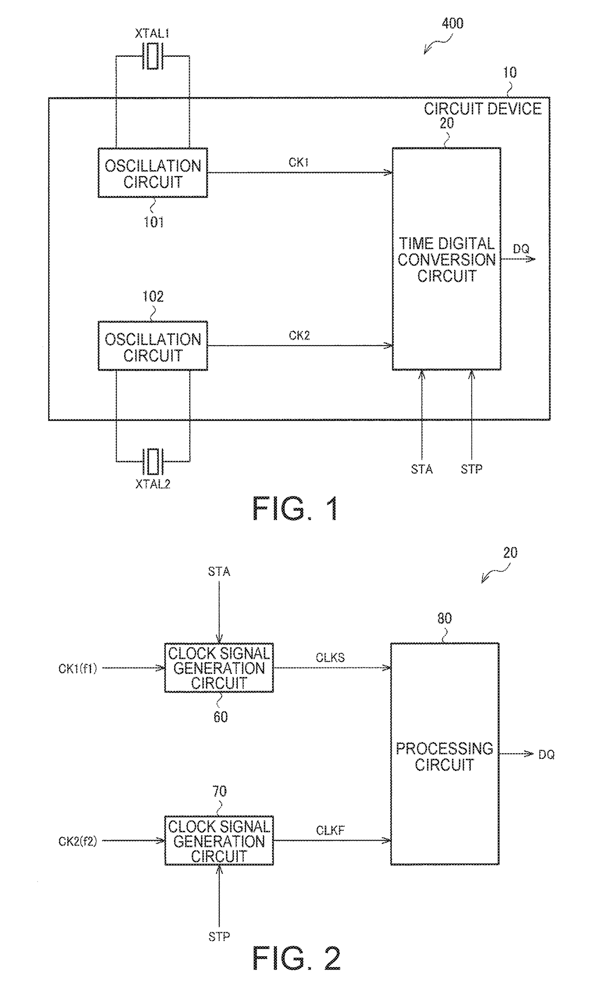
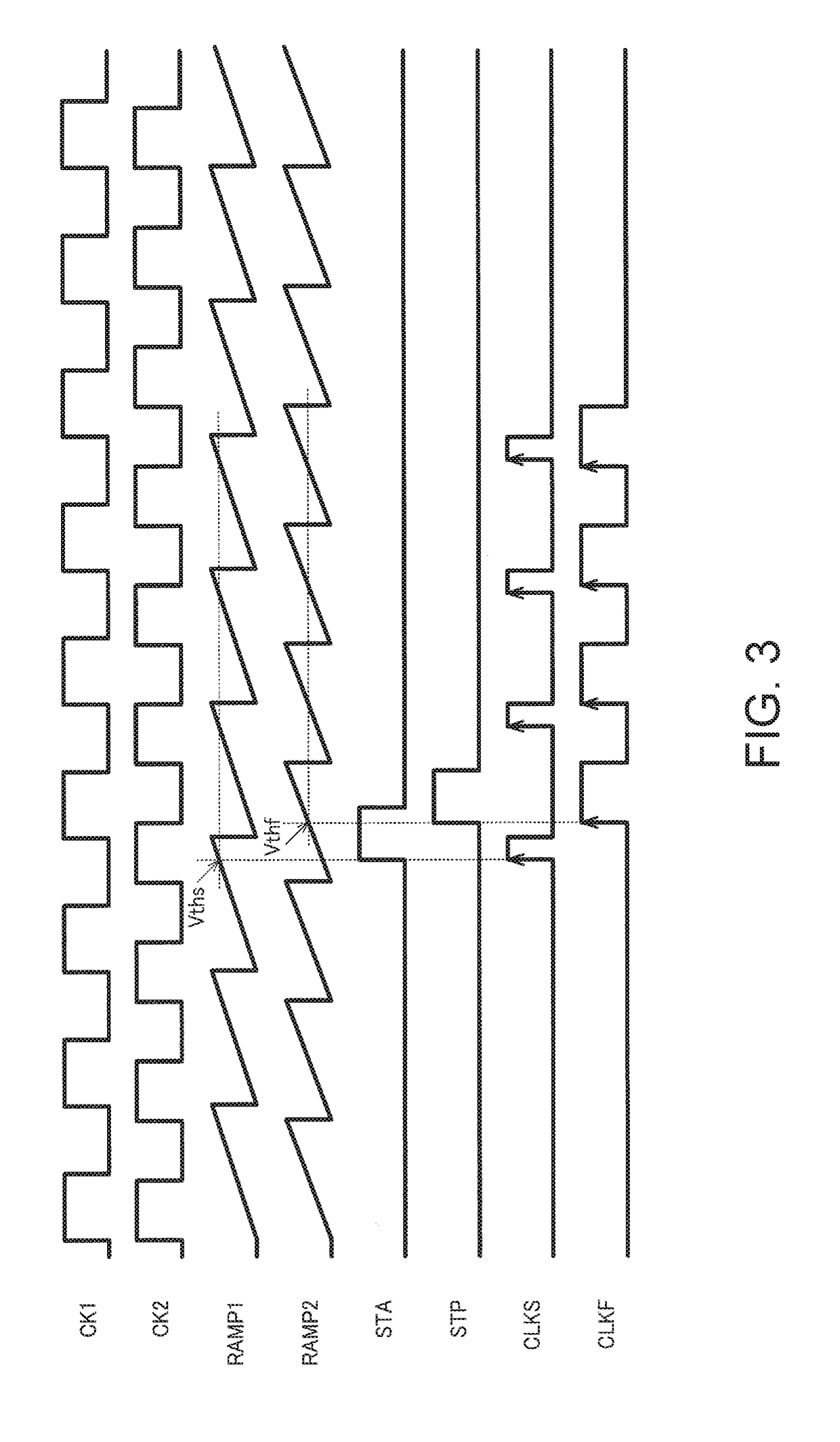
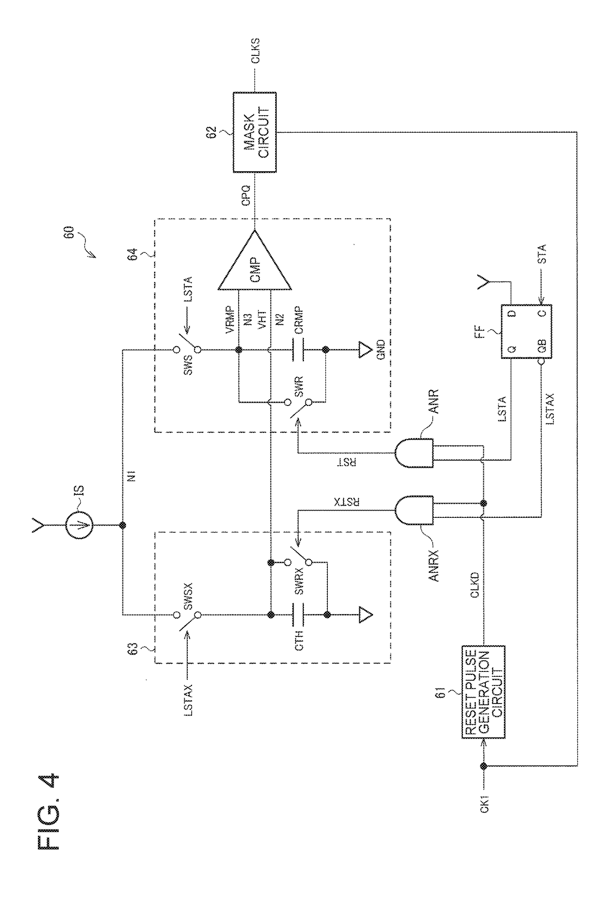
[0048]FIG. 1 shows a first example of the configurations of a circuit device including a time-to-digital converter according to the present embodiment and a physical quantity measurement apparatus including the circuit device. A physical quantity measurement apparatus 400 includes an oscillator XTAL1 (first oscillator oscillator), an oscillator XTAL2 (second oscillator), and a circuit device 10. The physical quantity measurement apparatus does not necessarily have the configuration shown in FIG. 1, and a variety of variations are conceivable, for ...


PUM


Abstract

A time-to-digital converter includes a clock signal generation circuit that generates a first cycle signal having a voltage level that monotonously increases or decreases in a cycle corresponding to the clock frequency of a reference clock signal and further generates a first clock signal based on a first signal and the first cycle signal, a clock signal generation circuit that generates a second cycle signal having a voltage level that monotonously increases or decreases in a cycle corresponding to the clock frequency of a reference clock signal and further generates a second clock signal based on a second signal and the second cycle signal, and a processing circuit that converts a time difference between the transition timing of the first signal and the transition timing of the second signal into a digital value based on the first and second clock signals.

Description

BACKGROUND1. Technical Field[0001]The present invention relates to a time-to-digital converter, a circuit device, a physical quantity measurement apparatus, an electronic apparatus, a vehicle, and the like.2. Related Art[0002]There has been a known time-to-digital converter that converts time into a digital value. As an example of a time-to-digital converter of related art that measures a time difference between a first signal and a second signal produced at arbitrary timings, there are, for example, related-art technologies disclosed in JP-A-64-079687 and JP-A-62-228191.[0003]JP-A-64-079687 describes a time clocking circuit that includes a first oscillator that starts oscillating at a frequency f when a start signal is produced and a second oscillator that starts oscillating at a frequency f+Δf in when a stop signal is produced and compares the phase of a clock signal from the first oscillator with the phase of a clock signal from the second oscillator to measure the time gap betwe...

Claims


Application Information

Patent Timeline
IPC IPC(8): G04F10/00H03K5/26G06F1/06
CPCG04F10/005H03K5/26G06F1/06H03B5/32H03B5/04H03K19/20H03D13/005
Inventor SUDO, YASUHIROHANEDA, HIDEO
Owner SEIKO EPSON CORP
Learn More