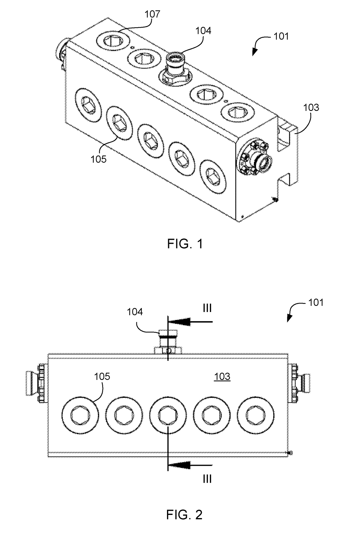
Fluid end with curved internal cavity profile

a technology of internal cavity and fluid end, which is applied in the direction of pump components, positive displacement liquid engines, liquid fuel engine components, etc., can solve the problems of gap always present above the mating surface and seal, and achieve the effect of reducing internal stresses, reducing internal stresses, and increasing laminar flow of proppan

Inactive Publication Date: 2019-03-07
ST9 GAS & OIL LLC
View PDF10 Cites 18 Cited by
  • Summary
  • Abstract
  • Description
  • Claims
  • Application Information

AI Technical Summary

Benefits of technology

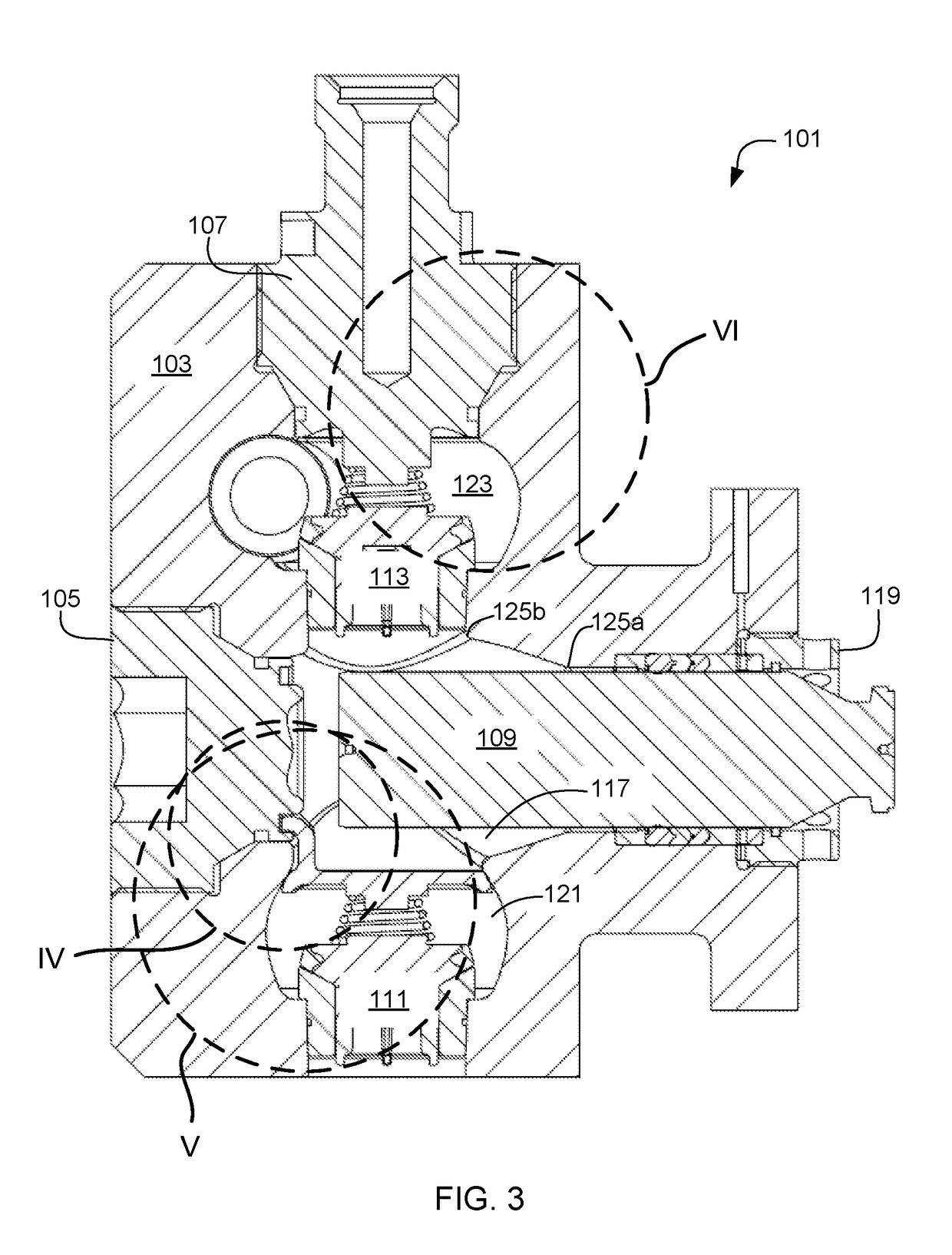
[0006]It is an object of the present application to provide a fluid end assembly that reduces internal stresses through the incorporation of curved internal cavity profiles. This design is to reduce the internal stresses on the fluid end in operation by optimizing the internal profile of the cavities to produce a more laminar flow of the proppant. The addition of these profiles to the internal cavities and components mitigate the turbulent and cavitation present in the proppant.
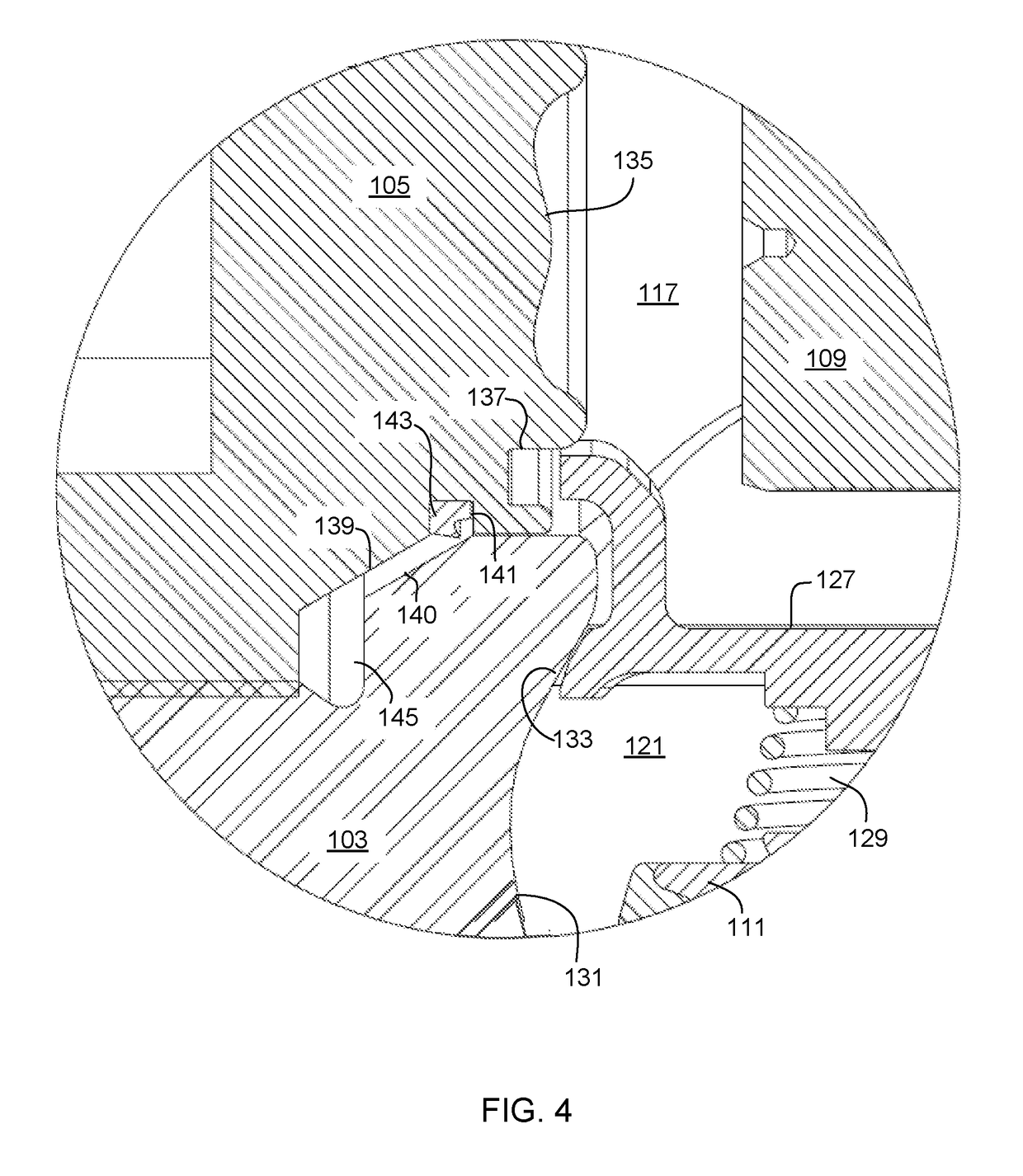
[0008]The suction plug is composed of a single member wherein the traditional plug and nut are combined together. The inner surface of the suction plug has a radiused profile. The discharge plug and the suction plug have mating faces and an adjacent recessed seal. As the plugs are threaded into location, the seal rides the chamfer thereby compressing the seal to the conforming diameter. The intersection of the chamfer start point and the seal groove is the same as the seal diameter. Therefore, no extrusion gap is created and the seal can not extrude so as to increase the feature life. Additionally, when fully seated, a gap is always present above the mating surfaces and seal.
[0009]Furthermore, it is a further object to provide a curved profile in the suction cavity of the fluid end. A spring retainer is seated in the suction cavity to hold the spring that operates the valve. A flat face is machined into the curved profile of the suction cavity to align the spring retainer in position and prevent the spring retainer from moving through the bore cavity. The suction plug includes the radiused features which help to guide the spring retainer into position during assembly and stops it from rotating circumferentially relative to the bore diameter.

Problems solved by technology

Additionally, when fully seated, a gap is always present above the mating surfaces and seal.

Method used


Image

  • Fluid end with curved internal cavity profile
  • Fluid end with curved internal cavity profile
  • Fluid end with curved internal cavity profile

Examples


Embodiment Construction

[0022]Illustrative embodiments of the preferred embodiment are described below. In the interest of clarity, not all features of an actual implementation are described in this specification. It will of course be appreciated that in the development of any such actual embodiment, numerous implementation-specific decisions must be made to achieve the developer's specific goals, such as compliance with system-related and business-related constraints, which will vary from one implementation to another. Moreover, it will be appreciated that such a development effort might be complex and time-consuming but would nevertheless be a routine undertaking for those of ordinary skill in the art having the benefit of this disclosure.

[0023]In the specification, reference may be made to the spatial relationships between various components and to the spatial orientation of various aspects of components as the devices are depicted in the attached drawings. However, as will be recognized by those skille...


PUM


Abstract

A fluid end assembly includes a fluid end and a plurality of valve assemblies each located within a cavity that has curved internal profiles. The curved internal profiles of the cavities are concaved outward. A plunger is included to provide variations in pressure within the fluid end so as to facilitate movement of the working fluid. A discharge plug is included in communication with the fluid end. The discharge plug may include a curved profile along an inner surface that corresponds with one of the cavities therein. A suction plug is releasably coupled to the fluid end and includes a curved profile along an inner surface. The suction plug also includes a recess for acceptance of a spring retainer. The spring retainer is included to support a suction valve assembly.

Description

CLAIM OF PRIORITY[0001]This application claims the benefit of U.S. Provisional Application No. 62 / 555,546, filed 7 Sep. 2017. The information contained therein is hereby incorporated by reference.BACKGROUND1. Field of the Invention[0002]The present application relates generally to a reciprocating pump, and in particular to a fluid end having a curved internal cavity profile for the reduction of turbulent flow and cavitation in the system.2. Description of Related Art[0003]It is difficult to economically produce hydrocarbons from low permeability reservoir rocks. Oil and gas production rates are often boosted by hydraulic fracturing, a technique that increases rock permeability by opening channels through which hydrocarbons can flow to recovery wells. During hydraulic fracturing, a fluid is pumped into the earth under high pressure (sometimes as high as 50,000 PSI) where it enters a reservoir rock and cracks or fractures it. Large quantities of proppants are carried in suspension by ...

Claims


Application Information

Patent Timeline
Patent Type & Authority Applications(United States)
IPC IPC(8): F04B53/16F04B53/10
CPCF04B53/16F04B53/1087F04B53/1032F04B1/0448F04B1/0461F04B1/053
Inventor BUCKLEY, CHRIS
Owner ST9 GAS & OIL LLC
Why Eureka
Try Eureka