Thermal management device for vehicle

a technology of thermal management device and vehicle, which is applied in the direction of mechanical equipment, machines/engines, transportation and packaging, etc., can solve the problems of affecting the traveling of the vehicle, affecting the cooling performance, and insufficient flow rate of cooling water, so as to suppress the heat loss caused by the mixing of heat medium

Active Publication Date: 2019-03-14
DENSO CORP
View PDF1 Cites 12 Cited by
  • Summary
  • Abstract
  • Description
  • Claims
  • Application Information

AI Technical Summary

Benefits of technology

[0024]Since the reserve tank is configured not to be in communication with the plurality of heat medium circuits at the same time, it can be prevented that the heat medium from the plurality of heat medium circuits are mixed through the reserve tank. As such, the heat loss due to the mixing of the heat medium can be suppressed.

Problems solved by technology

In particular, in a system having a high temperature, the cooling performance is largely deteriorated due to the air, which largely affects traveling of the vehicle.
Accordingly, corrosion of pipes may accelerate, and the pump performance may deteriorate, which results in an insufficient flow rate of the cooling water.
In a cooling system provided with an air conditioning circuit, when the cooling water containing air therein flows into an air-conditioning heat exchanger of an air conditioner, an air trapping sound goes through an inside of a vehicle compartment, which gives an occupant an uncomfortable feeling.

Method used


Image

  • Thermal management device for vehicle
  • Thermal management device for vehicle
  • Thermal management device for vehicle

Examples


first embodiment

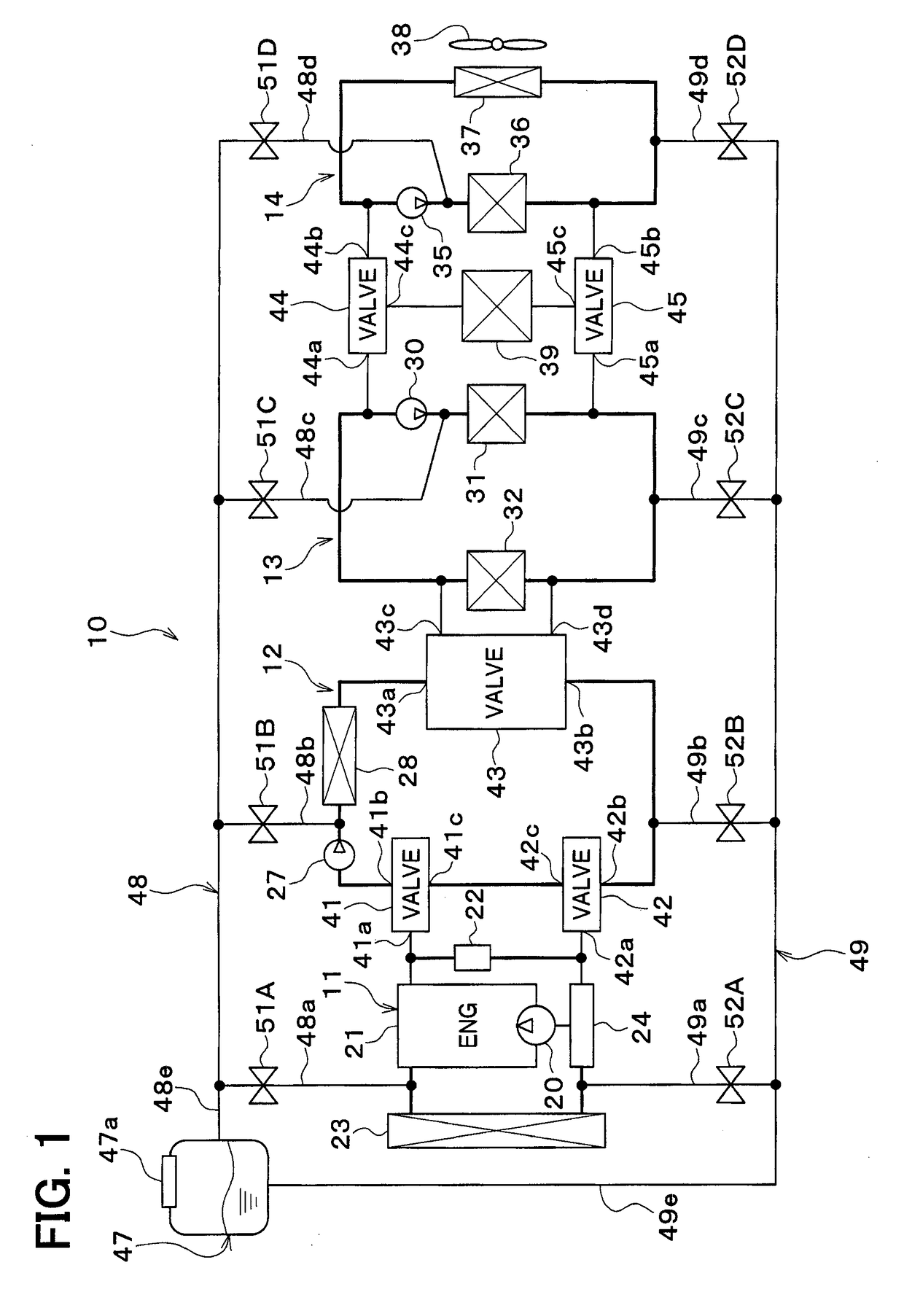
[0032]A thermal management device 10 for a vehicle illustrated in FIG. 1 is used for adjusting temperatures of various devices mounted to the vehicle and a temperature of the inside of a vehicle compartment to an appropriate temperature. In the present embodiment, the thermal management device 10 for a vehicle is applied to a hybrid vehicle that generates driving force for moving the vehicle from an engine and an electric motor.

[0033]The hybrid vehicle in the present embodiment is configured as a plug-in hybrid vehicle that is configured to charge a battery mounted to the vehicle with power supplied from an external power source while the vehicle is stopped. For example, the battery may be a lithium ion battery.

[0034]The driving force generated by the engine is used for operating a motor generator, and for moving the vehicle as well. Power generated by the motor generator and power supplied from the external power source can be stored in the battery. The power stored in the battery ...

second embodiment

[0201]In the above-described embodiment, a connection target circuit to be connected with the reserve tank 47 is set by operating the first to fourth inlet valves 51A-51D and the first to fourth outlet valves 52A-52D. In the present embodiment, the connection target circuit is set by operating a first to fifth valve 41-45.

[0202]That is, in the present embodiment, the first to fifth switching valves 41-45 serve as a connector that allows the reserve tank 47 to come in communication with the cooling water circuits 11-14 selectively.

[0203]In the present embodiment, the second switching valve 42 is a four-way valve including four ports. The second-circuit outlet pipe 49b of the outlet pipe 49 is connected to a fourth port 42d of the second switching valve 42.

[0204]In the present embodiment, the fourth switching valve 44 is a four-way valve including four ports. The third-circuit inlet pipe 48c of the inlet pipe 48 is connected to the fourth port 44d of the fourth switching valve 44.

[020...


PUM


Abstract

A thermal management device for a vehicle includes heat medium circuits, a reserve tank, and a connector. The heat medium circulates through the heat medium circuits separately. The reserve tank is configured to separate an air bubble contained in the heat medium from the heat medium. The connector allows the reserve tank to come in communication with the heat medium circuits selectively. As such, an occurrence of the heat loss in the degassing performed in the reserve tank can be suppressed with the thermal management device for a vehicle including the heat medium circuits.

Description

CROSS REFERENCE TO RELATED APPLICATION[0001]The present application is based on Japanese patent application No. 2016-032051 filed on Feb. 23, 2016, the content of which is incorporated herein by reference.TECHNICAL FIELD[0002]The present disclosure relates to a thermal management device for a vehicle.BACKGROUND ART[0003]As a conventional technique, Patent Literature 1 describes a cooling system provided with a plurality of cooling circuits. The conventional technique is provided with a supercharger cooling circuit and an engine cooling circuit.[0004]In the conventional technique, a common reserve tank is connected to the supercharger cooling circuit and the engine cooling circuit. The common reserve tank performs pressure management in the supercharger cooling circuit and the engine cooling circuit and performs degassing for a coolant. The degassing for the coolant may mean removing air from the coolant by separating the coolant into gas and liquid.PRIOR ART LITERATUREPatent Literat...

Claims


Application Information

Patent Timeline
Patent Type & Authority Applications(United States)
IPC IPC(8): F01P11/02B60H1/08B60K11/04F01P3/20F01P7/16F01P11/06
CPCF01P11/028B60H1/08B60K11/04F01P3/20F01P7/16F01P11/06F01P11/029F01P2011/066B60H1/00F01P2060/08B60H1/00885B60H2001/00307B60K11/02F01P7/165F01P2050/24B60H1/00278F01P2060/045B60H1/004
Inventor ENOMOTO, NORIHIKOKATO, YOSHIKIHASHIMURA, NOBUYUKISUGIMURA, KENGOMIURA, KOJISATO, KEIGOMARASIGAN, ARIEL
Owner DENSO CORP
Why Eureka
Try Eureka