
Laminate Solar Concentrator

a solar concentrator and lamp technology, applied in the field of optical elements, can solve the problems of concentrated devices not providing all the desired aspects, namely simultaneous precision, energy loss, maintenance costs, etc., and achieve the effects of simplifying maintenance, reducing barriers to replacement, and enhancing durability

Inactive Publication Date: 2019-03-14
HELIAC APS
View PDF3 Cites 1 Cited by
  • Summary
  • Abstract
  • Description
  • Claims
  • Application Information

AI Technical Summary

Benefits of technology

This patent aims to provide a new method for producing solar concentrators that is cheaper and more durable. The invention also includes a much faster production method that can produce larger areas of concentrators. Overall, this invention aims to reduce the cost of solar energy and make it more accessible to everyone.

Problems solved by technology

In the areas of Concentrated Solar Power (CSP) or Concentrated Photo Voltaics (CPV) in particular, the concentrators have failed to provide all the desired aspects, namely simultaneous precision, low weight, durability, large deflection angles, low energy loss, low maintenance costs, high durability and especially low cost.
However, due to the parabolic shape, there is a practical and economical limit of the width of the parabolic mirrors, which today is about 6-7 meters.
Imaging Fresnel lenses use curved segments and produce sharp images, while non-imaging lenses use flat segments, and do not produce sharp images.
This approach typically results in relatively heavy constructions, with a weight on the order of 11 kg of steel and 18 kg of glass per square meter of reflector [2].
One challenge of using polymers is that they are susceptible to UV radiation.
However, these plates are relatively expensive, so if one could further reduce the cost and material usage of the focusing elements, this would be economically and environmentally desirable.
While certain of the prior art discussed above addresses the problem of providing for easy cleaning of optical elements in the context of solar concentrators, none addresses the problem of renewal of the efficiency of the optical elements once the lifetime of the element is exceeded, for example as a result of UV damage, damage by scratching from windborne dust, and / or scratching resulting from repeated washing procedures.

Method used

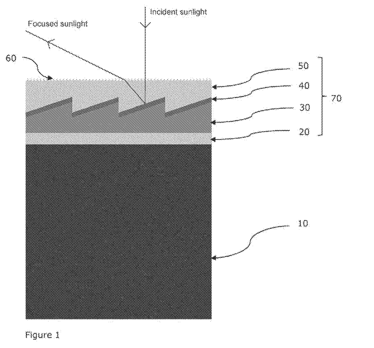
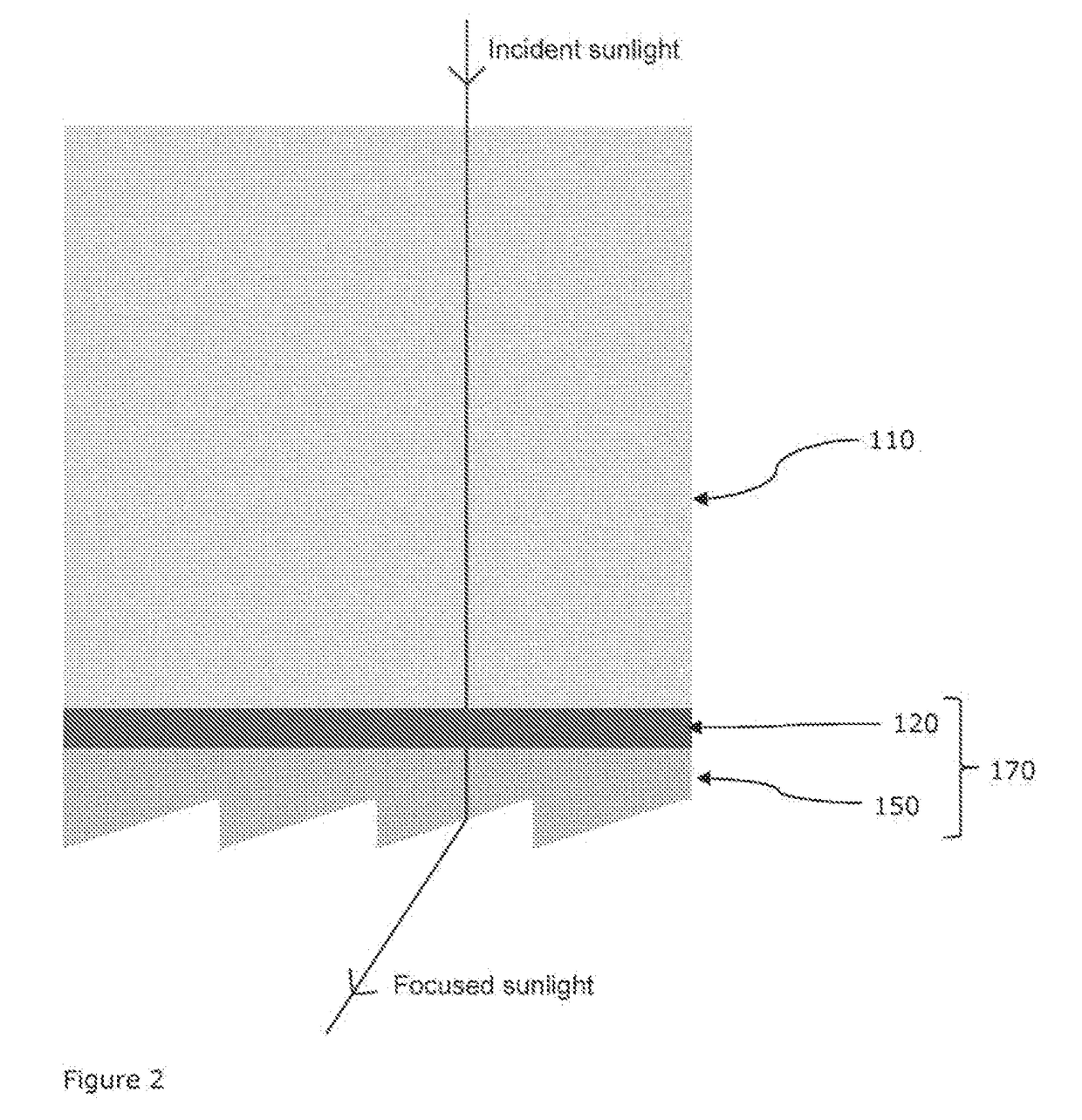
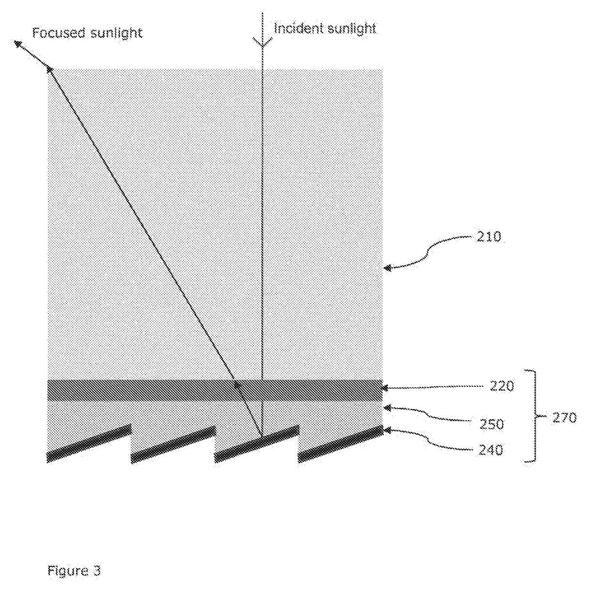

Image

  • Laminate Solar Concentrator
  • Laminate Solar Concentrator
  • Laminate Solar Concentrator

Examples


example 1

[0149]Two half-parts of a lens with dimensions 2200 mm×2800 mm and focal depth of 2200 mm is manufactured in a PET-Surlyn foil laminate, having a total thickness of 140 μm, resulting in a weight of approximately 160 g / m2. The foil laminate is coated by a pressure sensitive adhesive and laminated to a 4 mm mechanically rigid float glass (having a weight of approximately 10 kg / m2, thereby forming a stable optical element. The optical efficiency of the optical element is measured to 65%.

[0150]The stable optical element is mounted in a frame on a solar tracker. A water-based receiver is placed in the focal point absorbing the focused sunlight, thereby heating up the water, which is used for district heating.

[0151]After 3 years of use, the efficiency of the focusing part of the optical element (the foil laminate) has been lowered to 50% through weathering, abrasion and UV degradation. To restore the efficiency of the optical element, the focusing foil is being removed by applying a force...

example 2

[0152]A lens with dimensions 1450 mm×1450 mm and focal depth of 2000 mm is manufactured in a PET-PP foil laminate, having a total thickness of 150 μm, resulting in a weight of approximately 170 g / m2. The foil laminate is coated by a temperature sensitive adhesive and laminated to a 4 mm mechanically rigid float glass (having a weight of approximately 10 kg / m2, thereby forming a stable optical element. The optical efficiency of the optical element is measured to 75%. The stable optical element is mounted in a frame on a solar tracker. A thermal oil-based receiver is placed in the focal point absorbing the focused sunlight, thereby heating up the thermal oil, which is used for combined heating and power generation.

[0153]After 3 years of use, the efficiency of the focusing part of the optical element (the foil laminate) has been lowered to 65% through weathering, abrasion and UV degradation. To restore the efficiency of the optical element, the focusing foil is being removed by heating...

example 3

[0154]A reflective lens with dimensions 2200 mm×2800 mm and focal depth of 1200 mm is manufactured in a PET-PP-Aluminum foil laminate, having a total thickness of 300 μm, resulting in a weight of approximately 320 g / m2. The foil laminate is coated by a solvent sensitive adhesive and laminated to a 5 mm mechanically rigid aluminum plate (having a weight of approximately 12 kg / m2, thereby forming a stable optical element. The optical efficiency of the optical element is measured to 50%.

[0155]The stable optical element is mounted in a frame on a solar tracker. A thermal oil-based receiver is placed in the focal point absorbing the focused sunlight, thereby heating up the thermal oil, which is used for combined heating and power generation.

[0156]After 2 years of use, the efficiency of the focusing part of the optical element (the foil laminate) has been lowered to 35% through weathering, abrasion and UV degradation. To restore the efficiency of the optical element, the focusing foil is ...


PUM


Abstract

A focusing polymer foil for use in forming an optical element for use in a solar concentrator, and an optical element for use in a solar concentrator, arranged such that the focusing polymer foil is removable in order to renew the function of the optical element following damage and / or wear to the focusing polymer foil due to environmental conditions. A method of repair of such a damaged optical element, and methods of making the focusing polymer foil and optical element.

Description

FIELD OF THE INVENTION[0001]The present invention relates to an optical element for concentrating solar irradiation, and method and apparatus for manufacturing thereof.BACKGROUND OF THE INVENTION[0002]In many optical applications, concentrators or lenses are used to focus light. Many types of lenses have been demonstrated, classical refractive lenses, concave reflector lenses, flat lenses etc. In the areas of Concentrated Solar Power (CSP) or Concentrated Photo Voltaics (CPV) in particular, the concentrators have failed to provide all the desired aspects, namely simultaneous precision, low weight, durability, large deflection angles, low energy loss, low maintenance costs, high durability and especially low cost.[0003]WO2015 / 081961 describes an optical element for use as a linear solar concentrator, comprising a polymer foil with a lower Fresnel lens mirror structure and an optional upper antireflective layer, which greatly decreases internal losses found in typical Fresnel lens mir...

Claims


Application Information

Patent Timeline
IPC IPC(8): H01L31/054F24S23/30F24S23/70G02B19/00G02B5/09
CPCH01L31/0543F24S23/31F24S23/80G02B19/0023G02B19/0042G02B5/09G02B3/0031G02B3/08F24S2080/015F24S2025/601F24S21/00G02B5/0808Y02E10/52Y02E10/40
Inventor PRANOV, HENRIKMATSCHUK, MARIA
Owner HELIAC APS
Learn More