Method and apparatus for continuous gas monitoring using micro-colorimetric sensing and optical tracking of color spatial distribution

a color spatial distribution and micro-colorimetric technology, applied in the field of continuous gas monitoring using micro-colorimetric sensing and optical tracking of color spatial distribution, can solve the problems of limited to a single analyte in one sensor, poor selectivity, and high power consumption, and the need for frequent calibration

Active Publication Date: 2019-03-28
ARIZONA STATE UNIVERSITY
View PDF0 Cites 8 Cited by
  • Summary
  • Abstract
  • Description
  • Claims
  • Application Information

AI Technical Summary

Benefits of technology

[0009]This summary is provided to introduce, in a simplified form, a selection of concepts that are further described below in the Detailed Description. This summary

Problems solved by technology

These sensors include metal oxide semiconductors [11-13] and electrochemical sensors [14-16], but they suffer from poor selectivity, limitation to a single analyte in one sensor, high power consumption and need of frequent calibrations.
For this reason, most colorimetric sensors are for one-time use only, and lack the capability for continuous monitoring of analytes[17][18, 19].
However, all the methods mentioned above use a mechanical motor to rotate the roll of the sensor strip, or a pump to force air flow along the air channel, which adds cost to the device, increases energy consumption and device size, and requires periodic replacement or calibration.
More seriously, the inventors herein found that most mechanical motors or pumps tend to wear and degrade over time, which causes the rotation speed and flow rate to vary over time.
Because the reaction rate depends on the rotation speed and flow r

Method used


Image

  • Method and apparatus for continuous gas monitoring using micro-colorimetric sensing and optical tracking of color spatial distribution
  • Method and apparatus for continuous gas monitoring using micro-colorimetric sensing and optical tracking of color spatial distribution
  • Method and apparatus for continuous gas monitoring using micro-colorimetric sensing and optical tracking of color spatial distribution

Examples


example embodiments

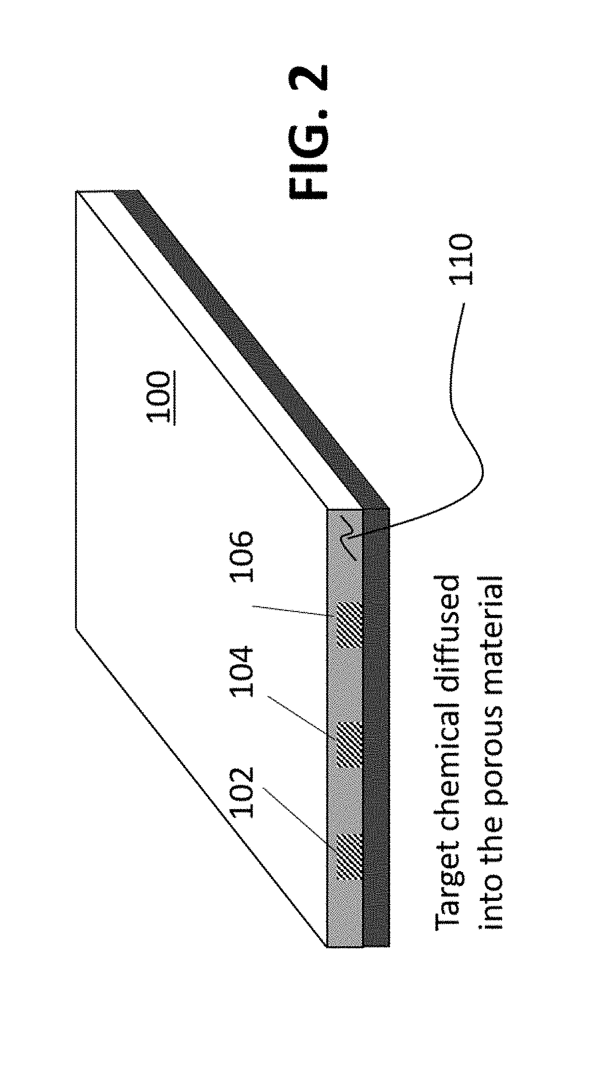
[0039]Referring now to FIG. 2, an example of a micro-colorimetric sensor is shown. wherein parallel linear channels of porous media are fabricated. A micro-colorimetric sensor 100 includes a plurality of parallel linear channels of porous media 102, 104, 106. Each linear channel includes a sensing material for one or several specific target chemicals in air. Each line can be separated by material 110 or can be next to each other. In some examples the porous media is selected from the group consisting of silica gel, cellulose, polymers, porous glass, silicon, metal oxides, metal nitrides, zeolites and combinations thereof.

[0040]Each of the sensing chemicals is selected for a particular target chemical, so that the sensor can simultaneously detect multiple chemicals. Air sample diffuses passively along each linear channel without using a pump, and the target chemical in the air sample reacts with the sensing chemical in the linear channel, starting from the inlet, which creates a colo...

example 1 continuous

Monitoring of Ozone Using Micro-Colorimetric Sensing and Optical Edge-Tracking

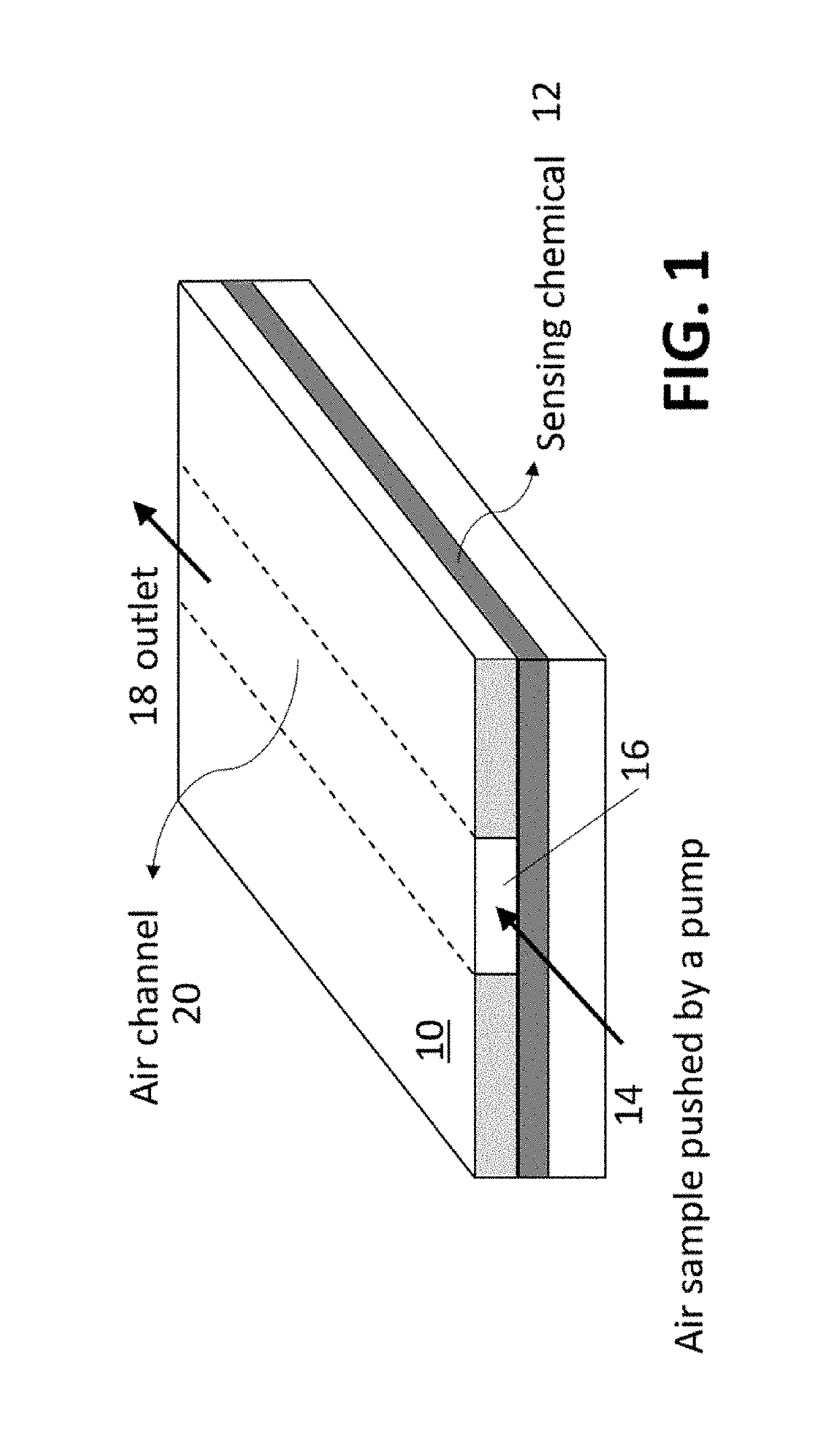
[0043]One example of micro-colorimetric sensor for continuous O3 monitoring was manufactured by a porous media and chemically responsive compounds. The porous media in this example was silica gel plate, purchased from Sorbent Technologies (Polyester backed silica G TLC plates). The silica gel plate was cut into 0.5 mm (width)×4 mm (length) small pieces and immersed in an aqueous solution with formulation of Indigo carmine and citric acid. Following by a 2-hour vacuum drying process, the micro-colorimetric O3 sensor was then covered with a piece of Acrylic and fixed by screws. The micro-colorimetric sensor was illuminated with a white LED (LEDtronics Inc.) and imaged with a CMOS imager (Logitech, Inc.) for real-time monitoring of the color progression continuously when exposed to O3 (FIG. 1a).

example 2

Micro-Colorimetric Sensor Array for Detection of Nitrogen Dioxide, Ozone, and Formaldehyde.

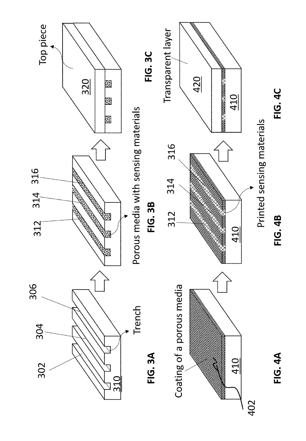
[0044]One example of micro-colorimetric sensor array for detection of Nitrogen Dioxide, Ozone, and Formaldehyde was fabricated by inkjet printing method. Silica gel was used as porous media and coated on polyester substrate. Three sensing solutions containing N,N-dimethyl-1naphthylamine, indigo carmine, and hydroxylamine sulfate respectively were prepared for selective detection of nitrogen dioxide, ozone, and formaldehyde. The three sensing solutions were inkjet printed on the porous silica gel layer in the form of three parallel lines. An acrylic plate was then affixed over the top surface of the porous silica layer to cover the three parallel linear channels. FIG. 10 are top views of the sensor array after exposing to ozone, nitrogen dioxide, and formaldehyde. Each sensing channel changed color and a clear color gradient was generated after exposing to the corresponding analyte, and there i...


PUM


Abstract

A micro-colorimetric sensor for sensing target chemicals that converts time sequence information into a spatial distribution of color. By tracking the spatial color distribution, chemical exposure over time is thus detected, which overcomes the limitation of traditional colorimetric sensors. A porous media is coated on a top surface of the substrate. Multiple sensing chemicals are fused in parallel linear channels into the porous media coating. A plate is affixed over the substrate top surface to cover the plurality of parallel linear channels. An air sample is diffused along the porous media to get a clear pattern of spatial color distribution and color images are captured. Optical parameters like gradient of spatial color distribution, intensity, and absorbance, etc., can be tracked to calculate analytes concentrations.

Description

CROSS-REFERENCE TO RELATED APPLICATION[0001]This application is a non-provisional application of currently co-pending U.S. Provisional Patent Application No. 62 / 564,143, filed Sep. 27, 2017, entitled “METHOD AND APPARATUS FOR CONTINUOUS MONITORING OF OZONE USING MICRO-COLORIMETRIC SENSING AND OPTICAL EDGE-TRACKING,” to the same inventors herein and claims the priority benefit of that filing date. Application No. 62 / 564,143 is incorporated by reference.STATEMENT REGARDING FEDERALLY SPONSORED RESEARCH OR DEVELOPMENT[0002]This invention was made with government support under U01 EB021980 awarded by the National Institutes of Health. The government has certain rights in the invention.TECHNICAL FIELD[0003]The present invention relates to a method and apparatus for continuous gas monitoring using micro-colorimetric sensing and optical tracking of color spatial distribution. More particularly, the method and apparatus utilize chemical diffusion in a medium, reaction of the chemical with a ...

Claims


Application Information

Patent Timeline
IPC IPC(8): G01N21/78G01N33/00
CPCG01N21/783G01N33/0039G01N33/0037G01N33/0047G01N2021/7763G01N2021/7793G01N2201/0621Y02A50/20
Inventor TAO, NONGJIANWANG, DILIN, CHENWEN
Owner ARIZONA STATE UNIVERSITY
Why Eureka
Try Eureka