Universal ac and DC input modular interconnectable printed circuit board for power distribution management to light emitting diodes

Active Publication Date: 2019-03-28
2449049 ONTARIO INC
View PDF5 Cites 1 Cited by
  • Summary
  • Abstract
  • Description
  • Claims
  • Application Information

AI Technical Summary

Benefits of technology

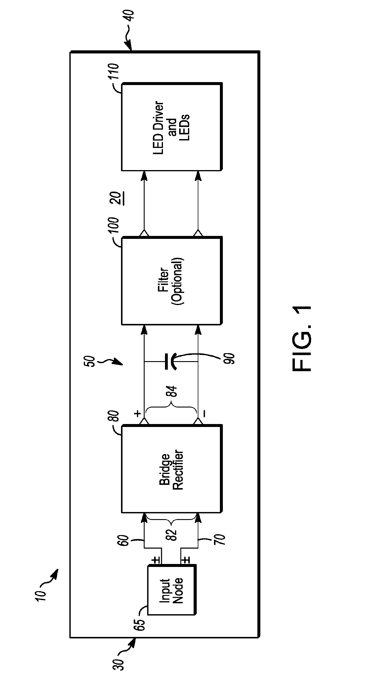
This patent is about a circuit board that has a power supply and can distribute power to different parts of the circuit. It has a single entry point for power and a way to pass current and signals through it. It also includes components to convert non-discreet input current to discreet output current and to minimize voltage fluctuations. The circuit board has at least two current paths, which ensures a constant current to the load, even if the input voltage changes. This technology allows for a more efficient and reliable distribution of power in a compact circuit design.

Problems solved by technology

There are challenges in design and implementation of such electrical systems especially in environments where space is tight and access is limited or power needs to be transmitted to the LED's are over long distances.
Rectifying the AC to DC conversion causes ripples in the voltage and current output from the driver to the LED.
Additional power conditioning may electrically be inefficient.
This solution requires more wiring, additional cavity of space to pass wires, and additional cost of parts and installations.
These solutions are labor intensive and expensive.
Maintenance and replacement of parts, inventory management, and schematic layouts are more complex with multiple fixtures.
Over wide voltage ranges these methods are not power efficient.
In such a design with 20% efficiency, the LED lights could consume up to 30 W per foot that would result in consumption of 2400 W power over an 80 foot train.

Method used


Image

  • Universal ac and DC input modular interconnectable printed circuit board for power distribution management to light emitting diodes
  • Universal ac and DC input modular interconnectable printed circuit board for power distribution management to light emitting diodes
  • Universal ac and DC input modular interconnectable printed circuit board for power distribution management to light emitting diodes

Examples


example 1

[0059]The following is an example of an alternative of the present disclosure and how it achieves constant LED drive current and constant LED light intensity.

Equipment

[0060]GW Instek Power supply, model PSW160-21.6, SN:GE0215052, Calibration cert:40715, Calibration date: 15 Dec. 16[0061]Gigahertz-optik photo sensor, model VL-3701-4, SN: 35074, Calibration: 1642622-WERK, Calibration date: January 2017[0062]Fluke Multimeter, model 177, SN: 40820352, Calibration: 44177, Calibration date: 24 Jan. 18

[0063]Procedure

[0064]Setup a light meter approximately 5 inches away from the LED light source;

[0065]Select dial on a multimeter to mA / A position and connect it in line with the LED string to measure LED drive current;

[0066]Turn on the power supply and setup the input voltage at 34 VDC;

[0067]Record the light level and measured LED drive current;

[0068]Increase input voltage and record the light level and LED drive current for each of the input voltage levels up to 168 VDC.

[0069]FIG. 6A-6D show...


PUM


Abstract

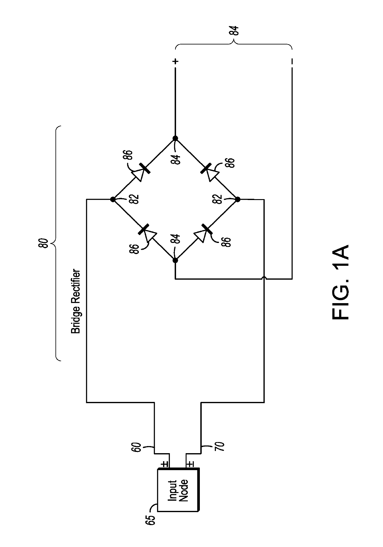
A continuous power distribution circuit board containing:i) A printed circuit board;ii) A universal power node;iii) At least one channel on the printed circuit board for passage of current, signal and combinations thereof throughout the board;iv) At least one bridge rectifier in communication with the universal power node for rectifying non-discrete input current to discrete output current;v) At least one capacitor in communication with the at least one bridge rectifier minimizing voltage potential fluctuation from the bridge rectifier;vi) At least one current load in communication with the at least one capacitor;wherein the continuous power distribution circuit board maintains a constant current to the at least one current load without any external current controller.

Description

FIELD OF THE DISCLOSURE[0001]The embodiments described herein relate generally to transit power management and distribution boards, in particular for Light Emitting Diode (LED) lighting, and particularly to power management and distribution in an LED lighting system using Printed Circuit Boards (PCB).BACKGROUND[0002]LED lighting systems are the lighting design of choice in many modern settings, notably in train and airplane cabins, due to high efficiency, low power consumption, long endurance and other advantages of LEDs. There are challenges in design and implementation of such electrical systems especially in environments where space is tight and access is limited or power needs to be transmitted to the LED's are over long distances. More specific to this disclosure, multiple voltage ranges may be used as the power input to the system that is normally handled by additional hardware.[0003]At the Integrated Circuit (IC) level, LEDs are current driven devices where the light intensit...

Claims


Application Information

Patent Timeline
IPC IPC(8): H05B33/08H05K1/18H05K1/02B60Q3/41B61D29/00H05B44/00
CPCH05B33/0842H05K1/181H05K1/0216H05B33/0896B60Q3/41H05B33/0815B61D29/00H05K2201/10015H05K2201/10106H05K2201/10166H05K2201/10022H05K2201/1006H05K1/0231B60Q3/43B60Q3/47H05B47/25H05B45/36H05B45/325H05B45/395H05B45/375H05B45/14H02M7/062H02M7/06H05B45/60
Inventor AUBERT, ANDREW CLARK BAIRD
Owner 2449049 ONTARIO INC
Why Eureka
Try Eureka