Method for determining diffusion radius of in-situ injection and remediation of contaminated soil and groundwater

a technology of diffusion radius and insitu injection, which is applied in the direction of shaft sinking, shaft equipment, instruments, etc., can solve the problems of increasing mechanical cost, affecting the success or failure of remediation projects, and the “dead angle” of remediation, so as to achieve mature and stable technology, low cost, and small disturbance to the formation

Active Publication Date: 2019-04-25
BCEG ENVIRONMENTAL REMEDIATION CO LTD
View PDF0 Cites 30 Cited by
  • Summary
  • Abstract
  • Description
  • Claims
  • Application Information

AI Technical Summary

Benefits of technology

[0035]1. The method of the present invention is suitable for determining and optimizing the effective diffusion radius of the in-situ injection remediation agent of the soil and groundwater (aquifer) in the shallow groundwater-rich site, and a reasonable diffusion radius design is beneficial to solve the problem of slurry-returning.
[0036]2. The points distribution of the present invention adopts triangular points distribution, and the row spacing and hole spacing design improves the operability of the engineering construction. Considering the difference in permeability of the remediation medium in the remediation site, the row spacing design parameters consider the diffusion effect of the remediation agent on the groundwater flow during the effective existence period of the underground environment, such as the groundwater flow in the high permeability formation such as sand. The low permeability formation such as clay layer does not consider the influence of groundwater flow, and the holes spacing design does not consider the influence of groundwater flow.
[0037]3. The present invention adopts various methods and methods such as observation method+on-site tracer method, on-site rapid test+laboratory test, and the like, so that the accuracy and differential analysis of the parameters obtained is ensured. Among them, the bromide ion electrode method is convenient and fast. The ten round tracer method is designed in three groups of tests, each group consisting of 4 rounds, and the three groups of tests share 2 rounds, which meet the test requirements while saving test time and cost.
[0039]5. Test the diffusion effect after in-situ injection, groundwater sampling adopts direct-push fixed-depth quick-sampling, which has the following characteristics: the technology is mature and stable, the pipe diameter is small, the accessories can be reused after washing, the cost is low, the disturbance to the formation is small, the sampling efficiency and the resolution are high, and the true and accurate tracer data capture is facilitated.

Problems solved by technology

Whether the design is reasonable or not directly affects the success or failure of the remediation project.
If the value is designed to be too large, the remediation area cannot be completely covered, resulting in remediation “dead angle”.
If the value is designed to be too small, serious slurry-returning is caused, greatly increasing mechanical cost.
However, this method is difficult to apply to the test of the diffusion radius of the remediation agent based on water solubility.
For the complicated hydrogeological conditions, the contaminated site does not pass the field test to determine the effective diffusion radius parameters, which has greater blindness.
The injection well itself has poor adaptability to the clay layer, and it also limits its application in clay-based sites.
The low injection pressure is difficult to apply methods such as observation.
However, the method is suitable for the diffusion of gaseous medium in soil and groundwater, and the application range is narrow.
This method is improved compared with the empirical method, but it still cannot solve the problem of the penetration diffusion radius of the remediation agent under high pressure injection conditions.
An agent injection points distribution method proposed by Chinese invention patent No. 201510159423.2 “A method for in-situ remediation of chromium contamination”, does not consider the influence of groundwater flow, and the engineering construction is poor in operability.
In addition, the in-situ remediation method of the invention has the disadvantage that the holes distribution method does not consider the influence of the groundwater flow during the effective reaction period of the remediation agent according to the difference in the permeability of the soil layer, and the overlapping area is too large and uneconomical.
The traditional hollow auger or prepacked monitoring well is set up, which takes a long time, high cost, large pipe diameter, requires packing operation, and has large disturbance to the ground layer, which is not conducive to obtaining true and accurate tracer data capture.
Sampling by mechanical bladder pump with manual operation requires low cost, has secondary filtration of the pump body with screen, small disturbance, is easy to obtain representative samples; sampling by the small stainless steel belle tube has large disturbance, and there is no secondary screen filtration, and the sample is easy to be turbid; in addition, the slow washing well sampling has complex system, requires electric drive, and the installation is cumbersome, the cost is high and uneconomical.
There are disadvantages such as small volume of the agent dispensing station and low injection efficiency, and the stability of the effective diffusion radius data is poor.

Method used


Image

  • Method for determining diffusion radius of in-situ injection and remediation of contaminated soil and groundwater
  • Method for determining diffusion radius of in-situ injection and remediation of contaminated soil and groundwater
  • Method for determining diffusion radius of in-situ injection and remediation of contaminated soil and groundwater

Examples


embodiment 1

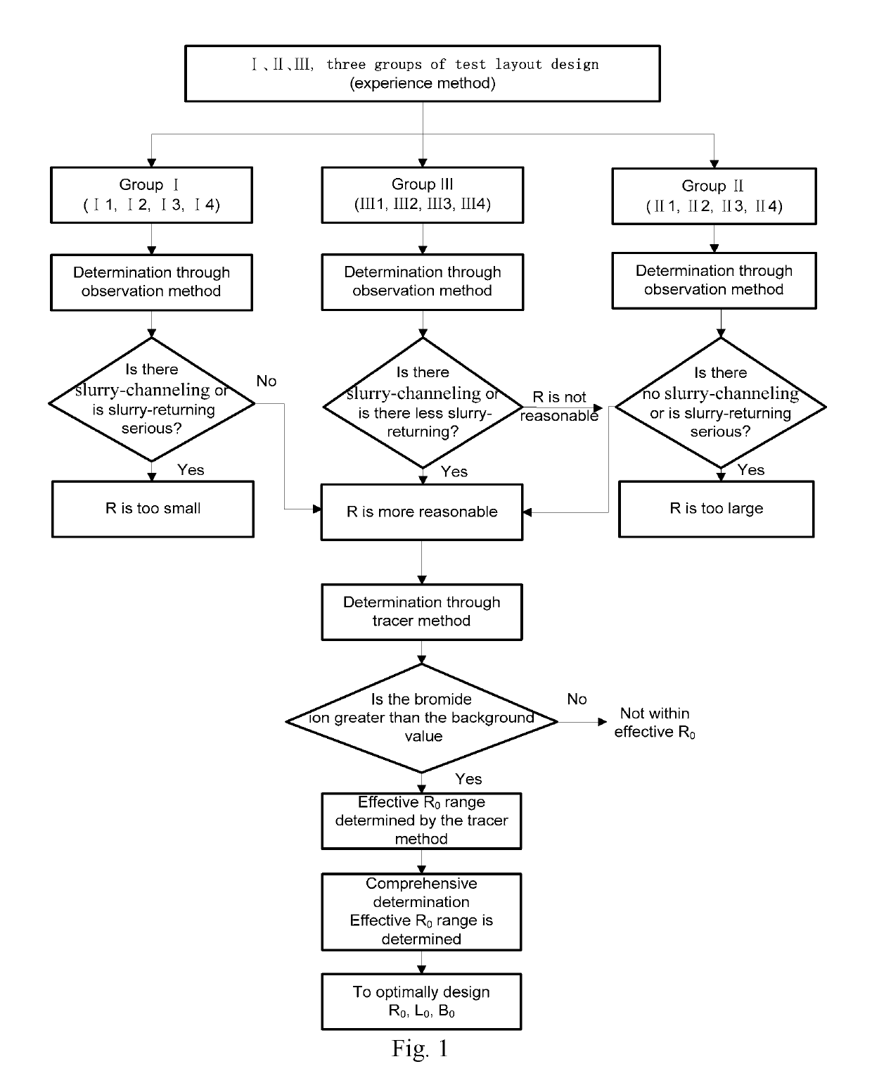
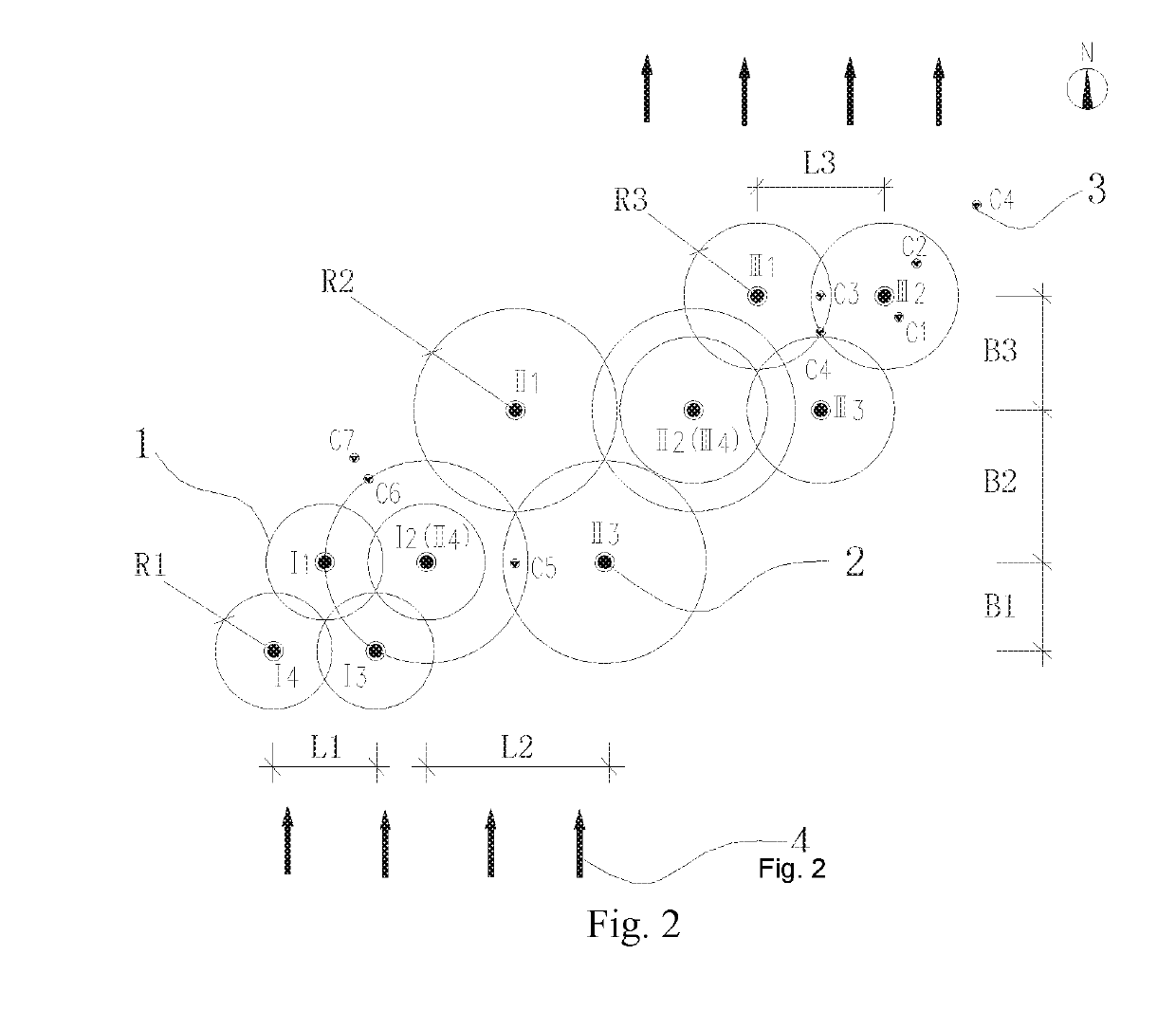
[0069]The present embodiment is an on-site test method for determining the effective diffusion radius of an organic contaminated soil and a groundwater remediation project by using an in-situ chemical oxidation in-situ injection method. The operations not specifically described in the present embodiment are carried out in accordance with the methods already given in the Summary of the Invention.

[0070]This project is a soil and groundwater remediation project of a chemical plant in Nanjing. The maximum remediation depth of the soil in this site is 12 m. There are two layers of silty clay layer and the aquifer is fine sand layer (distributed at 3˜6 m or 4˜7 m). The groundwater is shallow (about 1 m) and rich. The target contaminants in soil and groundwater are VOCs / SVOCs organic substances such as chlorobenzene, benzene, and P / O-nitrochlorobenzene. One of the difficulties in in-situ remediation of this project is the lack of practical experience and design basis for the diffusion radi...

embodiment 2

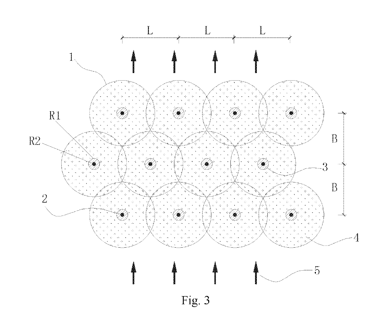
[0085]As shown in FIGS. 3 and 4, the present embodiment is an optimization process for in-situ injection of remediation holes distribution parameters of soil and groundwater. This is a process for optimizing the holes distribution parameters, based on the factors such as the groundwater flow at the remediation site, the difference in the permeability of the soil layer, and the effective reaction time of the remediation agent, in the case where the effective diffusion radius is obtained in Embodiment 1. Briefly read as follows:

[0086]In Embodiment 1, the recommended values of the effective diffusion radius of two typical soil layers are obtained. R0 for sands (such as fine sand aquifer) is 2.9 m, and R0 for clays (such as silty clay) is 0.9 m. The holes distribution method is a triangle method, and holes distribution method 1 is for sands. Considering the influence of groundwater flow on the row spacing of the holes distribution parameters, the row spacing increases the effective reac...


PUM

PropertyMeasurementUnit
depthaaaaaaaaaa
concentrationaaaaaaaaaa
outer diameteraaaaaaaaaa

Abstract

A method for determining the diffusion radius of in-situ injection and remediation of contaminated soil and groundwater. According to the triangle method, the hole spacing is perpendicular to the groundwater flow direction, the row spacing is along the groundwater flow direction, and the flow diffusion in the groundwater during the effective time of the remediation agent reaction is considered. Under high pressure rotary injection, the remediation agent and a certain proportion of bromide ions are simultaneously injected into the aquifer as a tracer. The diffusion of the agent is determined by observing the phenomenon of slurry-returning and slurry-channeling of adjacent injection points. After the completion of the injection, the groundwater is quickly sampled in fixed depth, the tracer concentration is quickly detected on site, and the concentration of bromide ions in the groundwater is compared with the background value. Comprehensive determination determines the optimal diffusion radius.

Description

TECHNICAL FIELD[0001]The present invention relates to a method for determining the diffusion radius of in-situ injection and remediation of contaminated soil and groundwater, belong to the technical field of remediation and monitoring method for contaminated soil and groundwater.BACKGROUND TECHNOLOGY[0002]Groundwater contamination and remediation have received much attention in recent years. Many in-situ remediation technologies for groundwater, such as permeable reactive barrier (PRB), pump-& treatment, in-situ chemical remediation, and in-situ microbial remediation, have been applied domestically. The in-situ injection technology has lower energy consumption than the mixing technology, and thus is more widely used, especially in the field of groundwater remediation. The good permeability of the aquifer is beneficial to the addition of a highly water-soluble remediation agent. The important reason for the in-situ remediation technology being favored is that it can solve the problem...

Claims


Application Information

Patent Timeline
Patent Type & Authority Applications(United States)
IPC IPC(8): G01N13/00B09C1/00B09C1/08G01N33/24
CPCG01N13/00B09C1/002B09C1/08G01N33/24B09C2101/00G01N2013/003B09C1/00E21B47/11E21D1/00
Inventor YANG, YUEWEILI, SHUPENGZHANG, YUEZHANG, XIAOBINGUO, LILICUI, SHUANGCHAOSONG, XIAOWEICHEN, FANYIN, PENGCHENGLIU, PENGLIU, YANNIU, QIANG
Owner BCEG ENVIRONMENTAL REMEDIATION CO LTD
Why Eureka
Try Eureka