Liquid container

Inactive Publication Date: 2019-05-02
SEIKO EPSON CORP
View PDF13 Cites 2 Cited by
  • Summary
  • Abstract
  • Description
  • Claims
  • Application Information

AI Technical Summary

Benefits of technology

This patent describes a liquid container with a layer structure that prevents the evaporation of organic solvents and the production of unintended substances. The container includes a gas barrier layer and a moisture barrier layer to prevent moisture from entering the container and reaching the gas barrier layer. The adhesive layer may also be eliminated to prevent a reduction in its function due to the evaporation of organic solvents. The layer structure includes a co-extruded layer that prevents the formation of an adhesive layer and suppresses a reduction in the function of the adhesive layer caused by organic solvents. The inner heat seal layer is also thicker to reduce the possibility of inner bag damage due to liquid pressure. The liquid container may also include a surface protection layer for added protection.

Problems solved by technology

For the multi-layered container, when an adhesive layer for bonding adjacent layers is used, the following problems may occur depending on the position at which the adhesive layer is formed.
In this case, the solvent component of the adhesive layer is dissolved by the evaporated organic solvent, which may reduce the function (bonding function) of the adhesive layer.
When the function of the adhesive layer is reduced, delamination occurs, which may reduce the impact resistance of the container.

Method used


Image

  • Liquid container
  • Liquid container
  • Liquid container

Examples


first embodiment

A. First Embodiment

A-1: Configuration of Liquid Consumption System

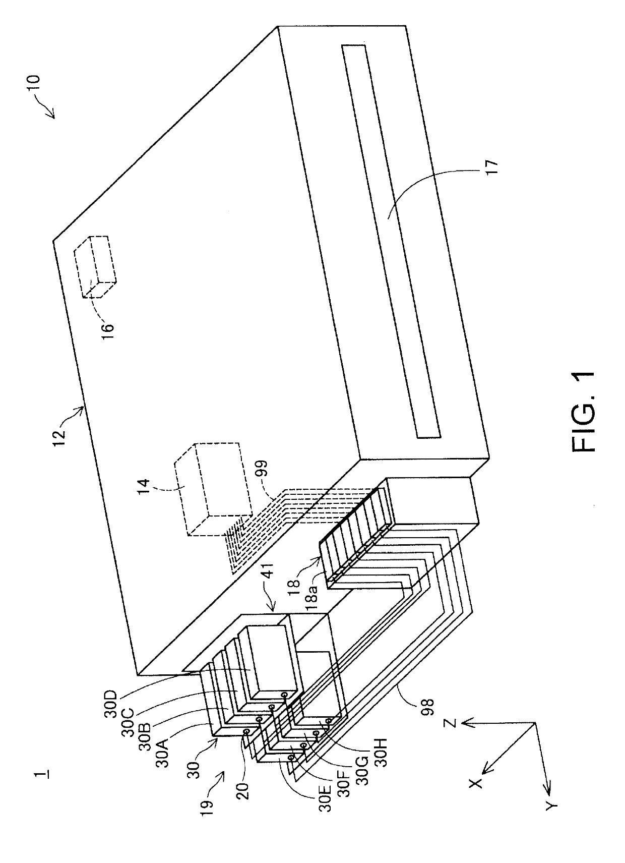
[0034]FIG. 1 is a schematic diagram of a liquid consumption system 1 according to a first embodiment of the present invention. In FIG. 1, three mutually orthogonal spatial axes, namely, an X axis, a Y axis, and a Z axis, are shown. The direction that extends along the X axis will be defined as the X axis direction, the direction that extends along the Y axis will be defined as the Y axis direction, and the direction that extends along the Z axis will be defined as the Z axis direction. In an attached state in which a liquid container 30 is attached to an attachment portion 20, which will be described later, the gravity direction (downward direction) will be defined as the −Z axis direction, and the counter gravity direction (upward direction) will be defined as +Z axis direction. Likewise, in the attached state, one side of the X axis direction will be defined as the +X axis direction, and the other side of the X axis...

second embodiment

B. Second Embodiment

[0087]FIG. 11 is a diagram illustrating a layer structure 800a of a liquid container 30a according to a second embodiment. The liquid container 30a according to the second embodiment and the liquid container 30 according to the first embodiment are different in that they have different layer structures 800 and 800a. As in the first embodiment, a liquid containing portion 32a is a double bag formed by an inner bag 320a and an outer bag 330a. Also, as in the first embodiment, the liquid containing portion 32a is a pillow-type bag-like body formed by thermally fuse-bonding outer peripheral portions of a first film member 340a and a second film member 350a. The first film member 340a and the second film member 350a have the same layer structure 800a.

[0088]The layer structure 800a includes, in order from the inside toward the outside, a first inner heat seal layer 611 that serves as a heat seal layer, a gas barrier layer 612, a second inner heat seal layer 613 that s...


PUM

PropertyMeasurementUnit
Structureaaaaaaaaaa

Abstract

The present invention provides a technique for a multi-layered container that includes an adhesive layer for bonding adjacent layers, with which it is possible to reduce the possibility of a problem such as a reduction in the function (bonding function) of the adhesive layer occurring. A liquid container for supplying a liquid to a liquid consumption apparatus includes a liquid containing portion, a connection portion that allows the liquid contained in the liquid containing portion to flow into the liquid consumption apparatus, and a housing box that houses the liquid containing portion. The liquid containing portion forms a layer structure in which a plurality of layers are disposed from the inside toward the outside. The layer structure includes an adhesive layer, a gas barrier layer that is provided inward of the adhesive layer, and a moisture barrier layer that is provided outward of the gas barrier layer.

Description

BACKGROUND1. Technical Field[0001]The present invention relates to a technique for a liquid container.2. Related Art[0002]An ink tank that includes a casing and a bag that is housed in the casing and has a spout is known (see, for example, Japanese Patent No. 4555550). Also, techniques for forming a multi-layered container that includes a gas barrier layer and a moisture barrier layer so as to obtain an air-tight and liquid-tight bag-like container are known (for example, Japanese Patents Nos. 4555550, 3896820, 4920422, and 4468018).[0003]Japanese Patent No. 4555550, Japanese Patent No. 3896820, Japanese Patent No. 4920422, and Japanese Patent No. 4468018 are the examples of related arts.[0004]For the multi-layered container, when an adhesive layer for bonding adjacent layers is used, the following problems may occur depending on the position at which the adhesive layer is formed. Specifically, when a liquid that contains an organic solvent as the main solvent is contained in the co...

Claims


Application Information

Patent Timeline
IPC IPC(8): B65D77/06B65D65/40B32B7/12B32B15/082B32B15/20B32B27/30
CPCB65D77/062B65D65/40B32B7/12B32B15/082B32B15/20B32B27/306B32B2307/7242B32B2307/7265B32B2439/62B65D77/067B32B2307/728B32B2307/31B32B2457/202B32B2307/546B32B2307/7246B32B2255/20B32B2439/40B32B27/32B32B7/04B32B2255/10B32B2307/7244B32B15/088B32B3/266B32B27/36B32B7/02B32B27/34B32B2307/558B32B2250/05B32B27/08B32B15/085B32B2255/205B32B3/08B32B15/09
Inventor KARASAWA, MASAHIROAOKI, YUJI
Owner SEIKO EPSON CORP
Why Eureka
Try Eureka