Physiological monitor for monitoring patients undergoing hemodialysis

a technology for monitoring patients and monitors, applied in the field of physiological monitors for monitoring patients undergoing hemodialysis, can solve the problems of nullifying values, affecting treatment, and measurement errors, so as to facilitate monitoring, improve repeatability and reproducibility of measurements, and improve patient monitoring.

Pending Publication Date: 2019-05-09
BAXTER INT INC +1
View PDF0 Cites 10 Cited by
  • Summary
  • Abstract
  • Description
  • Claims
  • Application Information

AI Technical Summary

Benefits of technology

[0023]In view of the foregoing, it would be beneficial to improve the monitoring of patients during hemodialysis and similar therapies. A sensor according to the invention, which facilitates monitoring a patient suffering from ESRD, HF, CHF, cardiac arrhythmias, and other diseases in both home and clinical environments, could achieve this goal. The sensor is worn like a patch or c

Problems solved by technology

Deviation in day-to-day placement of electrodes can result in measurement errors, particularly when trends of the measured parameters are extracted.
This, in turn, can lead to misinformation, nullify the value of such measurements, and thus negatively impact treatment.
Since each hemodialysis procedure involves removal of large volumes of fluid, it is not uncommon for a patient to experience intradialytic symptomatic hypotension, muscle cramps, nausea, vomiting, and other uncomfortable conditions.
However, such a weight can be erroneously influenced by a number of factors not related to fluid retention.
This condition occurs when SV and CO are insufficient in adequately perfusing the kidneys and lungs.
Chronic elevation of LVEDP causes transudation of fluid from the pulmonary veins into the lungs, resulting in shortness of breath (dyspnea), rapid breathing (tachypnea), and fatigue with exertion due to the mismatch of o

Method used


Image

  • Physiological monitor for monitoring patients undergoing hemodialysis
  • Physiological monitor for monitoring patients undergoing hemodialysis
  • Physiological monitor for monitoring patients undergoing hemodialysis

Examples


Embodiment Construction

1. Monitoring ESRD Patients During Hemodialysis

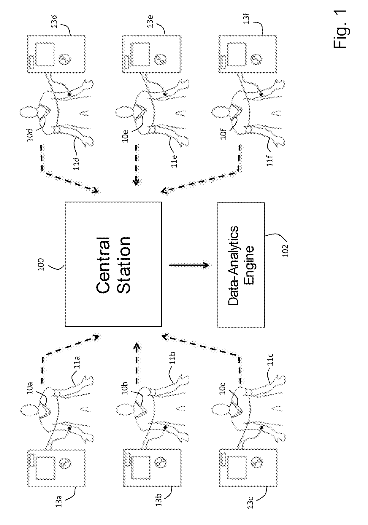
[0070]As illustrated in FIG. 1, a sensor 10a-f according to the invention can be used to measure a collection of ESRD patients 11a-f connected to individual dialysis machines 13a-f. The dialysis machines, for example, may be located in a single dialysis clinic. Each sensor 10a-f, as described in more detail below with reference to FIGS. 3 and 4 below, continuously measures a collection of time-dependent physiological waveforms (ECG, TBI, PPG, PCG), vital signs (HR, RR, TEMP, SpO2, and BP) and hemodynamic parameters (TFC, SV, CO) and then wirelessly transmits data indicating these parameters to a central station 100. The sensor 10a-f typically measures waveforms at relatively high frequencies (e.g. 250 Hz) compared to the vital signs and hemodynamic parameters (e.g. once every minute). The sensor 10a-f measures the time-dependent waveforms directly from the patient with embedded sensing elements, described in more detail below. Using com...


PUM


Abstract

The invention provides a system for characterizing a patient undergoing hemodialysis, featuring: 1) a body-worn biometric sensor, worn on a single location of the patient, and featuring: i) sensing elements for measuring electrocardiogram (ECG), thoracic bio-impedance (TBI), photoplethysmogram (PPG), and phonocardiogram (PCG) waveforms; ii) a processor for collectively analyzing the ECG, TBI, PPG, and PCG waveforms to determine a set of physiological parameters; and iii) a first wireless transceiver configured to transmit the set of physiological parameters; 2) a gateway system comprising a second wireless transceiver configured to receive the set of physiological parameters; and 3) a data-analytics system configured to analyze the set of physiological parameters to determine the patient's status.

Description

CROSS-REFERENCE TO RELATED APPLICATIONS[0001]This application claims the benefit of U.S. Provisional Application No. 62 / 346,410 filed Jun. 6, 2016, which is hereby incorporated in its entirety including all tables, figures, and claims.BACKGROUND AND FIELD OF THE INVENTIONField of the Invention[0002]The invention relates to the use of sensors that measure physiological signals from patients undergoing medical treatment, e.g. hemodialysis.General Background[0003]There are a number of physiological parameters that can be assessed by measuring physiological or physiologically influenced biometric signals from a patient. Some signals, such as electrocardiogram (ECG), thoracic bio-impedance (TBI), photoplethysmogram (PPG), and phonocardiogram (PCG) waveforms, are measured with sensors (e.g. electrodes, optics, microphones) that attach directly to the patient's skin. Processing of these waveforms yields parameters such as heart rate (HR), respiration rate (RR), heart rate variability (HRV)...

Claims


Application Information

Patent Timeline
IPC IPC(8): A61B5/00A61B5/0205A61M1/14
CPCA61B5/4836A61B5/6823A61B5/0205A61B5/0002A61B5/7225A61M1/14A61B5/02416A61B5/02108A61B2560/0223A61B5/0402A61B5/0537A61B5/029A61B7/04A61M2205/3303A61M2230/04A61M2230/65A61B5/02055A61B5/0816A61B2505/00A61M2205/3553A61M2205/3561A61M2230/63A61B5/1102A61B5/0295A61B5/282A61B5/318
Inventor BANET, MATTHEWDHILLON, MARSHAL SINGHPEDE, SUSAN MEEKSHAYWARD, LAUREN NICOLE MILLERDHILLON, MARK SINGHKLEIN, JEFFREYSTAINER, DEREKBROADBOOKS, R. CRAIG
Owner BAXTER INT INC
Why Eureka
Try Eureka