Method and device in ue and base station used for low latency communication

a low-latency communication and base station technology, applied in the field of radio signal transmission schemes, can solve the problems of reducing the transmission power affecting the performance of an uplink control channel, and power selection used for long stti transmission via a traditional power scaling method

Active Publication Date: 2019-05-23
SHANGHAI LANGBO COMM TECH CO LTD
View PDF17 Cites 2 Cited by
  • Summary
  • Abstract
  • Description
  • Claims
  • Application Information

AI Technical Summary

Benefits of technology

[0197]According to one aspect of the present disclosure, the above method is characterized in that, the seco

Problems solved by technology

Therefore, power selection used for the long sTTI transmission via a traditional power scaling method becomes a problem.
However, one of the most obvious problems of this method is

Method used


Image

  • Method and device in ue and base station used for low latency communication
  • Method and device in ue and base station used for low latency communication
  • Method and device in ue and base station used for low latency communication

Examples


embodiment 1

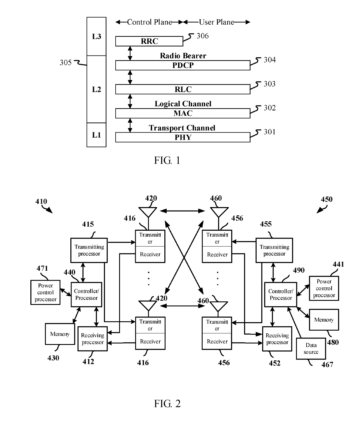
[0262]Embodiment 1 illustrates a schematic diagram of a radio protocol architecture of a user plane and a control plane according to the present disclosure, as shown in FIG. 1. FIG. 1 illustrates a schematic diagram of a radio protocol architecture of a user plane and a control plane. In FIG. 1, the radio protocol architecture of user equipment (UE) and Base Station Equipment (gNB or eNB) is represented by three layers, which are a layer 1, a layer 2 and a layer 3 respectively. The layer 1 (L1) 301 is the lowest layer and performs signal processing functions of each PHY layer. The layer 1 is called PHY 301 in this paper. The layer 2 (L2) 305 is above the PHY 301, and is in charge of the link between the UE and the gNB via the PHY 301. In the user plane, the L2 305 comprises a Medium Access Control (MAC) sublayer 302, a Radio Link Control (RLC) sublayer 303, and a Packet Data Convergence Protocol (PDCP) sublayer 304. All the three sublayers terminate at the gNB of the network side. A...

embodiment 2

[1] Embodiment 2

[0268]Embodiment 2 is a diagram illustrating a base station equipment and a given UE according to one embodiment of the present disclosure, as FIG. 2 shown. FIG. 2 is a diagram of gNB410 between access network and UE450.

[0269]Base station (410) comprises controller / processor 440, memory 430, receiving processor 412, transmitting processor 415, power control processor 471, transmitter / receiver 416 and antenna 420.

[0270]User equipment (UE450) comprises controller / processor 490, memory 480, data source 467, transmitting processor 455, receiving processor 452, power control processor 441, transmitter / receiver 456 and antenna 460.

[0271]In downlink transmission, a processing associated with a base station device (410) comprising:

[0272]Upper layer packet arrives at controller / processor 440, controller / processor 440 provides packet head compression, encryption, packet segmented connection, reordering and multiplexing demultiplexing between logic and transport channels, to im...

embodiment 3

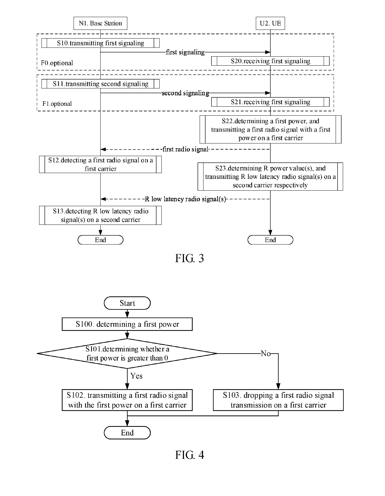
[0310]Embodiment 3 illustrates a flow chart of transmission of the first radio signal according to one of the present disclosures, as FIG. 3 shown. In FIG. 3, base station N1 is a maintenance base station of a serving cell of UE U2. Wherein steps identified in block F0 and block F1 are optional.

[0311]For base station N1, transmitting a first signaling in step S10; transmitting a second signaling in step S11; detecting a first radio signal on a first carrier in step S12; detecting R radio signal(s) on a second carrier in step S13.

[0312]For UE U2, receiving a first signaling in step S20; receiving a second signaling in step S21; determining a first power in step S22, and transmitting a first radio signal with a first power on a first carrier; determining R power value(s) in step S23; and transmitting R low latency radio signal(s) with R power value(s) on a second carrier respectively.

[0313]In embodiment 3, the first radio signal carries at least one of a first bit block and a first up...


PUM


Abstract

A method and device in a User Equipment (UE) and a base station low latency communication are disclosed. UE determines a first power, and transmits a first radio signal with the first power on a first carrier, and determines R power value(s), and transmits R low latency radio signal(s) on a second carrier with the R power value(s) respectively. When the first power and the R power value(s) have a value of zero, the UE drops the corresponding radio signals transmission. The present disclosure, according to carrying information of the first radio signal and the R low latency radio signal value(s) respectively, and time domain relations of occupied time intervals, determines the first power and the R power value(s), and then in a scenario that the UE supports both low latency communication and carrier aggregation, properly configures transmission powers of different carriers, and guarantees correct reception of uplink channels.

Description

CROSS REFERENCE TO RELATED APPLICATION[0001]This application is a continuation-in-part of International Application No. PCT / CN2017 / 094637, filed Jul. 27, 2017, claiming the priority benefit of Chinese Patent Application Serial Number 201610615909.7, filed on Jul. 31, 2016, and Chinese Patent Application Serial Number 201610621127.4, filed on Aug. 2, 2016, the full disclosure of which is incorporated herein by reference.BACKGROUNDTechnical Field[0002]The present disclosure relates to transmission schemes of radio signals in wireless communication systems, and in particular to a method and a device for low latency communication.Related Art[0003]In existing Long-term Evolution (LTE) and Long-Term Evolution Advanced (LTE-A) systems, Transmission Time Interval (TTI) or subframe or Physical Resource Block (PRB) pair corresponds to a milli-second (ms) in time. A LTE subframe comprises two time slots, a first time slot and a second time slot respectively, the first time slot and the second ...

Claims


Application Information

Patent Timeline
IPC IPC(8): H04W52/14H04W52/32
CPCH04W52/146H04W52/325H04W52/346H04W52/367
Inventor ZHANG, XIAOBO
Owner SHANGHAI LANGBO COMM TECH CO LTD
Why Eureka
Try Eureka