

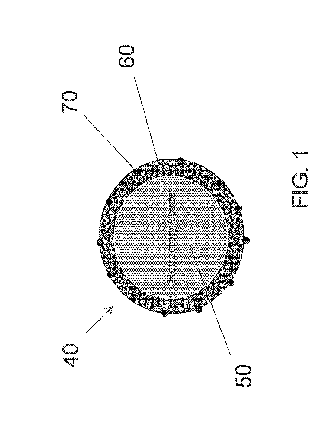
Core/shell catalyst particles and method of manufacture
a catalyst and shell technology, applied in the direction of physical/chemical process catalysts, metal/metal-oxide/metal-hydroxide catalysts, separation processes, etc., can solve the problems of low temperature operation, base metal oxides reacting with the support, and less effective catalysts used to treat the exhaust of internal combustion engines
- Summary
- Abstract
- Description
- Claims
- Application Information
AI Technical Summary
Benefits of technology
Problems solved by technology
Method used
Image

Examples
example 1
on of 10% CeO2 Shell & 90% La2O3-ZrO2 Core
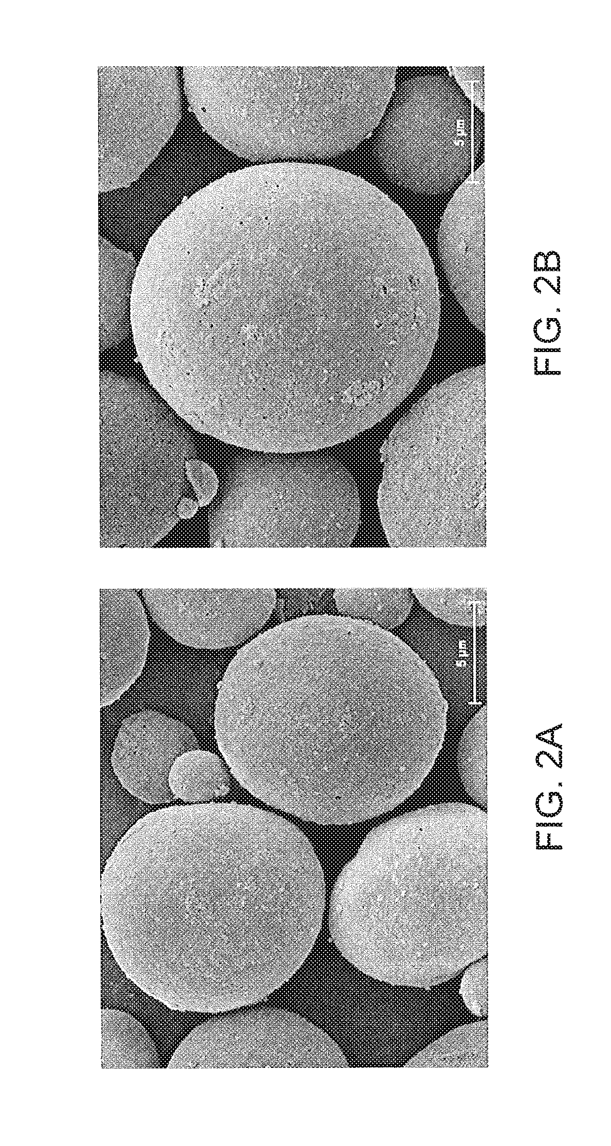
[0088]La2O3-ZrO2 core particles are composed of 8% La2O3 and 92% ZrO2. Add 750 grams of colloidal CeO2 (20% CeO2) to about 1630 grams of water. Slowly add 1369 grams of La2O3 (8%) / ZrO (92%) particles. Mix very well. Original particle size distribution at 90% (i.e., D90) is less than 65-70 μm. Mill the slurry to particle size distribution at 90% less than 4-5 μm. The final slurry properties are: pH=6.3 and solid 34.7%, and viscosity=12.5 cp. Spray dry powder the slurry to form a CeO2 shell with 10% CeO2 and core of 90% La2O3-ZrO2. Dry at 110° C. for 2 hours and calcine at 550° C. for 2 hours. Scanning electron microscope was used to determine the core-shell structure, as shown in FIGS. 2A and 2B.
example 2
on of 30% CeO2 Shell & 70% La2O3-ZrO2 Core
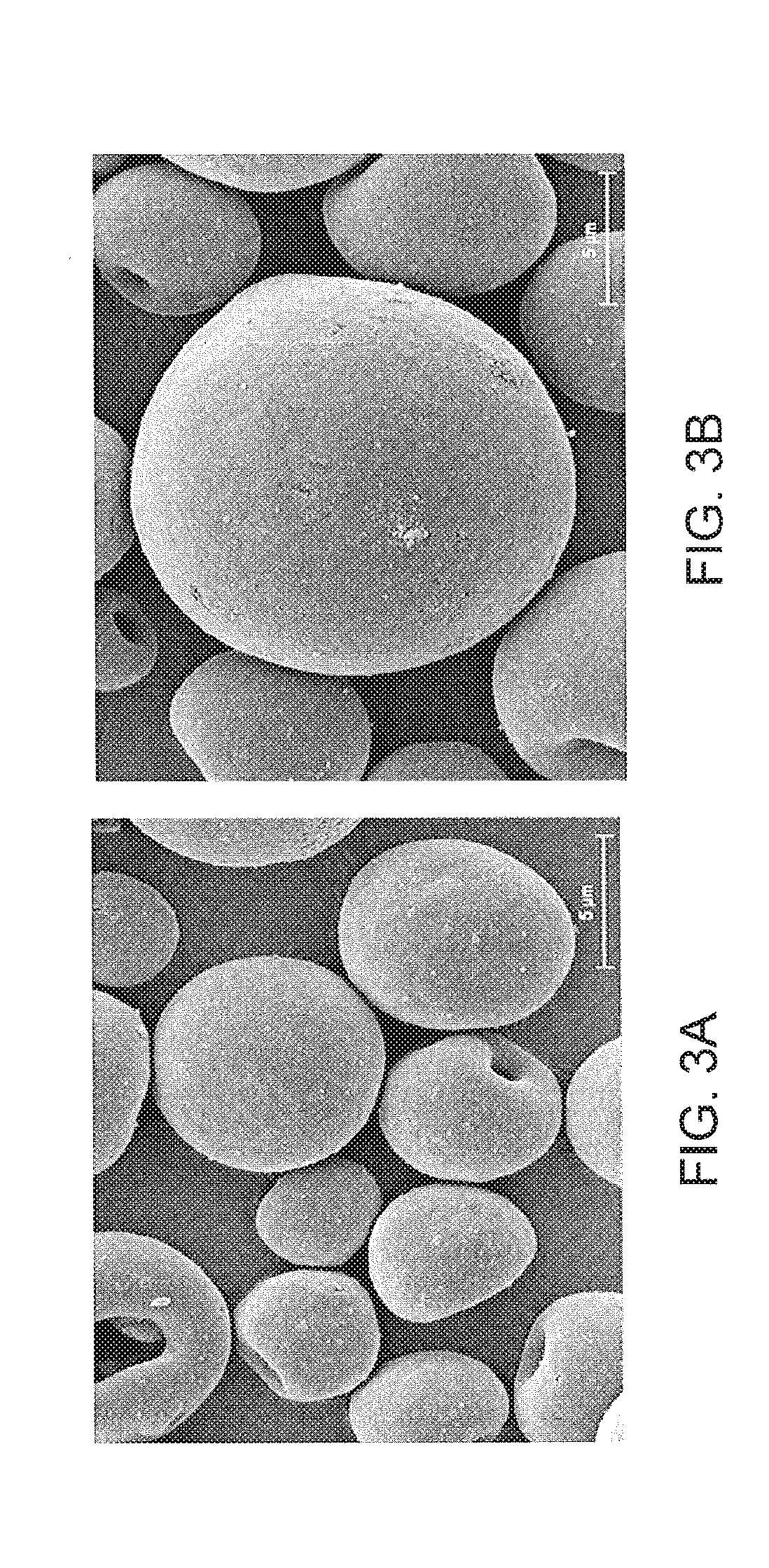
[0089]Add 2250 grams of colloidal CeO2 (20% / CeO2) to about 435 grams of water. Slowly add 1064 grams of La2O3 (8%) / ZrO (92%). Mix very well. Original particle size distribution at 90% is less than 65 μm. Mill the slurry to particle size distribution at 90% less than 4-5 μm. The final slurry properties are: pH=5.26 and solid 37.9%, and viscosity=9 cp. Spray dry powder the slurry to form a CeO2 shell with 30% CeO2 and Core of 70% La2O3-ZrO2. Dry at 110° C. for 2 hours and calcine at 550° C. for 2 hours. Scanning electron microscope was used to determine the core-shell structure, as shown in FIGS. 3A and 3B.
example 3
Three-Way Conversion (TWC) Catalyst Comprising Core-Shell Particles of Example 1
[0090]This example describes the preparation of a Three-Way Conversion (TWC) catalyst in the form of a two-layer wash coat design using inventive material described in Example 1. Separate Pd and Rh washcoats were applied onto a monolithic substrate (600 cells / in2 and 4 mil wall thickness). The Pd and Rh loadings are 47 and 3 g / ft3 respectively. The same monolithic substrate was used in all examples.[0091]a. First (Bottom) Pd Layer: Pd slurry was prepared by impregnating 30% of the Pd onto alumina followed by calcination at 550° C. The calcined Pd on alumina was then added to water to make a slurry with about 40% solids. The Pd on alumina slurry at pH of about 4-4.5 was then milled to particle size distribution at 90% less than 10-12 μm. The remaining Pd (70%) was applied onto ceria-zirconia material with composition: 40% CeO2, 50% ZrO2, and 10% La and Y oxides. The Pd on CeO2-ZrO2 was then made into a sl...
PUM
| Property | Measurement | Unit |
|---|---|---|
| particle size distribution d90 | aaaaa | aaaaa |
| particle size distribution d90 | aaaaa | aaaaa |
| thickness | aaaaa | aaaaa |
Abstract
Description
Claims
Application Information