Inverter device

a technology of inverter and heat storage material, which is applied in the direction of electric generator control, dynamo-electric converter control, dynamo-electric gear control, etc., can solve the problems of inability to appropriately control the temperature of the switching element, and the latent heat storage material has a problem with supercooling, so as to suppress the supercooling effect of the latent heat storage material

Inactive Publication Date: 2019-06-06
JTEKT CORP
View PDF0 Cites 4 Cited by
  • Summary
  • Abstract
  • Description
  • Claims
  • Application Information

AI Technical Summary

Benefits of technology

[0005]An object of the present invention is to provide an inverter device capable of suppressing supercooling of a latent heat storage material, and appropriately controlling the temperature of a switching element.

Problems solved by technology

However, the latent heat storage material has a problem with supercooling.
When the latent heat storage material is supercooled, the temperature of the switching element cannot be appropriately controlled.

Method used


Image

  • Inverter device
  • Inverter device
  • Inverter device

Examples


first embodiment

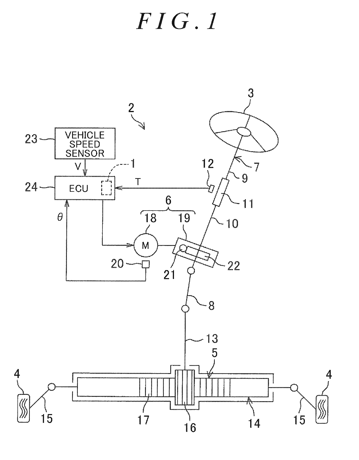
[0018]Hereinafter, exemplary embodiments of the present invention will be described in detail with reference to the accompanying drawings. In the exemplary embodiments, an inverter device is applied to an electric power steering system. FIG. 1 is a schematic diagram illustrating the general configuration of an electric power steering system 2 to which an inverter device 1 is applied according to the present invention. The electric power steering system 2 includes a steering wheel 3, a steering operation mechanism 5, and a steering assist mechanism 6. The steering wheel 3 is a steering member for steering the vehicle. The steering operation mechanism 5 steers steered wheels 4 in conjunction with rotation of the steering wheel 3. The steering assist mechanism 6 assists the driver in steering.

[0019]The steering wheel 3 and the steering operation mechanism 5 are mechanically coupled to each other via a steering shaft 7 and an intermediate shaft 8. The steering shaft 7 includes an input ...

second embodiment

[0082]FIG. 8 is a block diagram schematically illustrating the electrical configuration of an ECU 24 to which an inverter device 101 according to the present invention is applied. FIG. 9 is a cross-sectional view of a part corresponding to the part illustrated in FIG. 4, illustrating the general configuration of the inverter device 101 of FIG. 8. Elements corresponding to those of the inverter device 1 described above are denoted by the same reference numerals, and will not be further described.

[0083]Referring to FIGS. 8 and 9, the ECU 24 includes the inverter device 101 in place of the inverter device 1. The inverter device 101 differs in configuration from the inverter device 1. That is, the inverter device 101 does not include the limiter 82 or the limiter control unit 83, but includes a second radiator 102, a relay section 103, and a relay section control unit 108. The second radiator 102 is disposed away from the radiator 52. In this embodiment, the second radiator 102 is locat...


PUM


Abstract

An inverter device includes a radiator that includes a latent heat storage material transitioning between a solid phase region, a phase transition region, and a liquid phase region, in accordance with a temperature of the latent heat storage material, and that absorbs heat generated in switching elements, a temperature sensor that detects the temperature of the latent heat storage material, and a microcomputer. The microcomputer includes a determining unit that determines whether a condition is satisfied, the condition being that the temperature of the latent heat storage material is close to a melting point of the latent heat storage material, and that the temperature of the latent heat storage material is on a rising trend, and a supercooling suppressing unit that limits a motor current when the determining unit determines that the condition is satisfied.

Description

INCORPORATION BY REFERENCE[0001]The disclosure of Japanese Patent Application No. 2017-232921 filed Dec. 4, 2017 including the specification, drawings and abstract, is incorporated herein by reference in its entirety.BACKGROUND OF THE INVENTION1. Field of the Invention[0002]The present invention relates to an inverter device.2. Description of Related Art[0003]Japanese Patent Application Publication No. 2012-99612 (JP 2012-99612 A) discloses a semiconductor device including a latent heat storage material that absorbs the heat generated in a semiconductor element (switching element). The latent heat storage material transitions between a solid phase region corresponding to a solid state, a phase transition region where a solid state and a liquid state co-exist, and a liquid phase region corresponding to a liquid state, in accordance with the temperature thereof. The latent heat storage material absorbs heat energy when transitioning from the solid state to the liquid state, and releas...

Claims


Application Information

Patent Timeline
Patent Type & Authority Applications(United States)
IPC IPC(8): H02P21/16F28D20/02H02P27/12H02P21/22H02P21/18
CPCH02P21/16F28D20/028H02P27/12H02P21/22H02P21/18F28D2020/0008F28D2021/0028B62D5/0403B62D5/0409H01L23/373H02P27/06B62D5/0454B62D5/0463H02M7/5387H05K7/20945Y02E60/14H05K5/0211
Inventor KOUCHI, TATSUMA
Owner JTEKT CORP
Why Eureka
Try Eureka