Method And Apparatus For Surface Finishing And Support Material Removal (Deci Duo)

a technology of support material and surface finish, which is applied in the direction of chemistry apparatus and processes, cleaning using liquids, manufacturing tools, etc., can solve the problems of complex geometries which would never be possible, unfavorable parts production, and unwanted support material presence, so as to avoid damage to the part itself, the surface finish is smooth.

Active Publication Date: 2019-06-13
POSTPROCESS TECH INC
View PDF0 Cites 15 Cited by
  • Summary
  • Abstract
  • Description
  • Claims
  • Application Information

AI Technical Summary

Benefits of technology

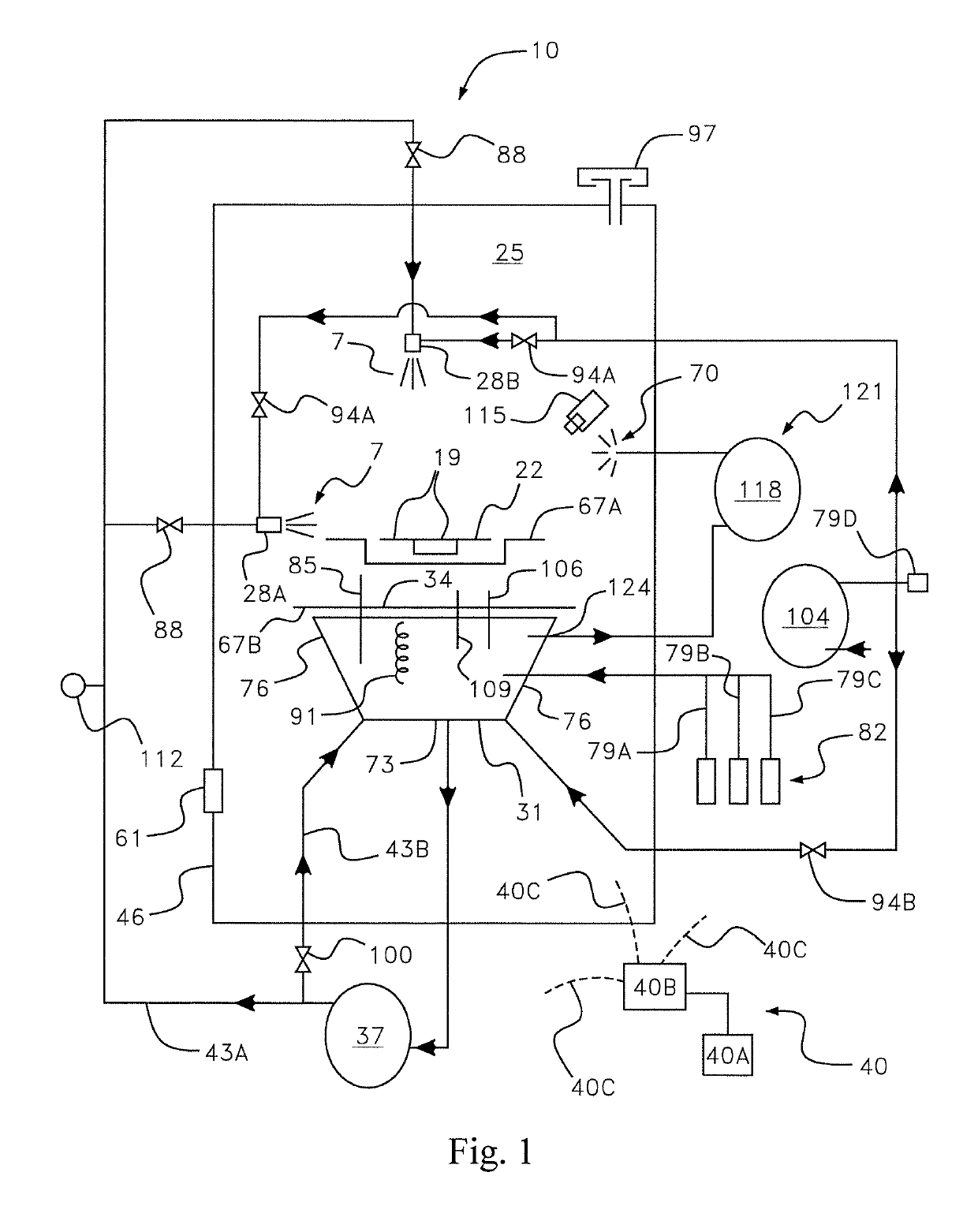
[0006]Disclosed herein are devices and methods to use mechanical agitation, fluid motion, chemical dissolution, and pressurized fluid having suspended solid media to smooth the surface finish and remove unwanted support material while avoiding damage to the part itself.

Problems solved by technology

These additive manufacturing techniques allow for the production of parts having complex geometries which would never be possible through traditional manufacturing techniques, such as casting, injection molding, or forging.
However, additive manufacturing suffers from substantial problems.
Two of these problems are the presence of unwanted support material and rough part surfaces.
The support material can itself have a complex geometry and be voluminous, especially when support material is needed in a plurality of areas.
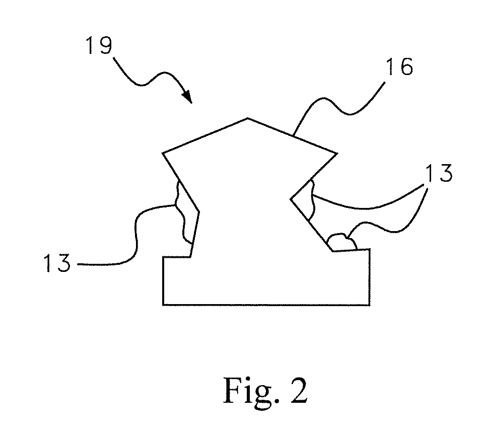
Additionally, since additive manufacturing creates a part in discrete layers, the surface finish of a part is rough, because each printed layer may not end precisely at a desired location, and may not form continuously with the next layer, thus leaving a rough outer surface.
This rough outer surface is visually unappealing and can cause stress concentrations, which could develop during testing or use of the part, leading to premature failure.
Depending on the type of part or its design, using manual labor could be cost prohibitive.
Additionally, with manual labor, it is difficult to avoid removing too much material and uneven surface finishing.
If a surface is finished unevenly, stress concentrations could still exist, leading to pre-mature failure.
Further, manual support removal and surface finishing lacks the ability to be consistent over an extended period of time, and it creates a bottleneck in the production process since one technician can clean only one part at a time.
In any event, it can take a long time to clean and smooth even one part, let alone a large number of parts.
However, these machines are limited in the type of process parameters that can be altered to improve the process, and also often require ongoing involvement during operation by a technician thus failing to completely eliminate the manual labor obstacle.
Additionally, if a technician is unaware that a machine is not set at the proper parameters, excessive material removal could occur, essentially ruining the part.

Method used


Image

  • Method And Apparatus For Surface Finishing And Support Material Removal (Deci Duo)
  • Method And Apparatus For Surface Finishing And Support Material Removal (Deci Duo)
  • Method And Apparatus For Surface Finishing And Support Material Removal (Deci Duo)

Examples


Embodiment Construction

[0026]It should be noted that like drawing numbers on different drawing views identify identical, or functionally similar, structural elements. It is to be understood that the invention is not limited to the disclosed aspects.

[0027]Furthermore, the invention is not limited to the particular methodology, materials, or modifications described. As such, the invention may vary from that which is disclosed herein. It is noted that the terminology used herein is for the purpose of describing particular embodiments and aspects of the invention.

[0028]Unless defined otherwise, all technical and scientific terms used herein have the same meaning as commonly understood to one of ordinary skill in the art to which the invention pertains. It should be understood that any methods, devices or materials similar or equivalent to those described herein may be used in the practice or testing of the method and apparatus.

[0029]Ranges of values are disclosed herein. The ranges set out a lower limit value...


PUM

PropertyMeasurementUnit
densityaaaaaaaaaa
distanceaaaaaaaaaa
distanceaaaaaaaaaa

Abstract

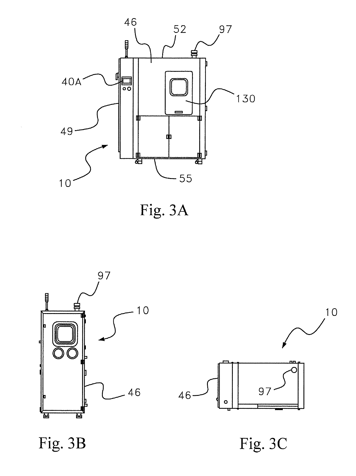
Apparatuses and methods for removing support material from and/or smoothing surfaces of an additive-manufactured part are disclosed. Apparatuses may include a spraying chamber, a support surface within the spraying chamber, and one or more nozzles having the ability to spray a fluid at the additive-manufactured parts. The fluid may include a liquid and solid particles carried by the liquid. The support surface may have the ability to support the additive manufactured part. The apparatus may include a tank having the ability to hold at least some of the fluid. A heater may be included for heating the fluid to a desired temperature.

Description

CROSS-REFERENCE TO RELATED APPLICATION[0001]This patent application claims the benefit of priority to U.S. provisional patent application Ser. No. 62 / 595,030, which was filed on Dec. 5, 2017 the entire disclosure of which is hereby incorporated by reference.FIELD OF THE INVENTION[0002]This invention relates generally to a method and apparatus for surface finishing and support material removal from parts made using additive manufacturing techniques such as 3D printing, and, more specifically, to a method and apparatus for surface finishing and support material removal from parts using mechanical agitation, fluid motion, chemical dissolution, and pressurized suspended solid media fluid to smooth the surface finish and remove unwanted support material without damaging the part.BACKGROUND OF THE INVENTION[0003]Additive manufacturing processes, including three dimensional (“3D”) printing, selective laser sintering (“SLS”), stereolithography (“SLA”), fused deposition modeling (“FDM”), mat...

Claims


Application Information

Patent Timeline
Patent Type & Authority Applications(United States)
IPC IPC(8): B29C64/35B33Y40/00B22F3/24B08B3/02B08B3/04B08B5/02
CPCB29C64/35B33Y40/00B22F3/24B08B3/02B08B3/04B08B5/02B22F2003/247B24C1/08Y02P10/25B22F10/40B29C71/0009B22F10/43B22F10/62B33Y40/20B29C64/40B29C64/393B24C1/00B33Y50/02B29C71/009
Inventor HUTCHINSON, DANIEL JOSHUA
Owner POSTPROCESS TECH INC
Why Eureka
Try Eureka