Plasma foreline thermal reactor system

a technology of thermal reactor and plasma foreline, which is applied in the field of vacuum processing techniques, can solve the problems of excessive reaction chamber downtime, damage to pumps, and pipe blockage, and achieve the effects of reducing the number of reactors, and improving the efficiency of the reactor

Active Publication Date: 2019-07-25
APPLIED MATERIALS INC
View PDF0 Cites 2 Cited by
  • Summary
  • Abstract
  • Description
  • Claims
  • Application Information

AI Technical Summary

Benefits of technology

[0010]In another embodiment, a method for preventing particles from accumulating in a vacuum pump and foreline of a vacuum processing system is provided. The method generally includes mixing a plasma with exhaust gas from the vacuum processing system and thereby forming an exhaust stream, cooling the plasma and exhaust gas mixture, and trapping particles formed from the plasma and exhaust gas mixture.

Problems solved by technology

The process gases used by CVD and other vacuum processing facilities include many compounds which must be abated or treated before disposal, due to regulatory requirements and environmental concerns.
If steps are not taken to prevent the reaction or condensation of the exhaust gases, pipes may be blocked and pumps may be damaged by the accumulation of chemicals deposited by the exhaust gases.
If there is no effective way to clean the undesired deposits from the equipment in situ, then the equipment must be removed or shut down for cleaning “off-line”.
If the equipment has to be opened to accomplish cleaning, this may lead to excessive reaction chamber down-time.
This problem exists in many types of vacuum processing chambers, such as etch reactors, ion implant chambers, plasma treatment chambers, atomic layer deposition chambers, and the like.

Method used


Image

  • Plasma foreline thermal reactor system
  • Plasma foreline thermal reactor system
  • Plasma foreline thermal reactor system

Examples


Embodiment Construction

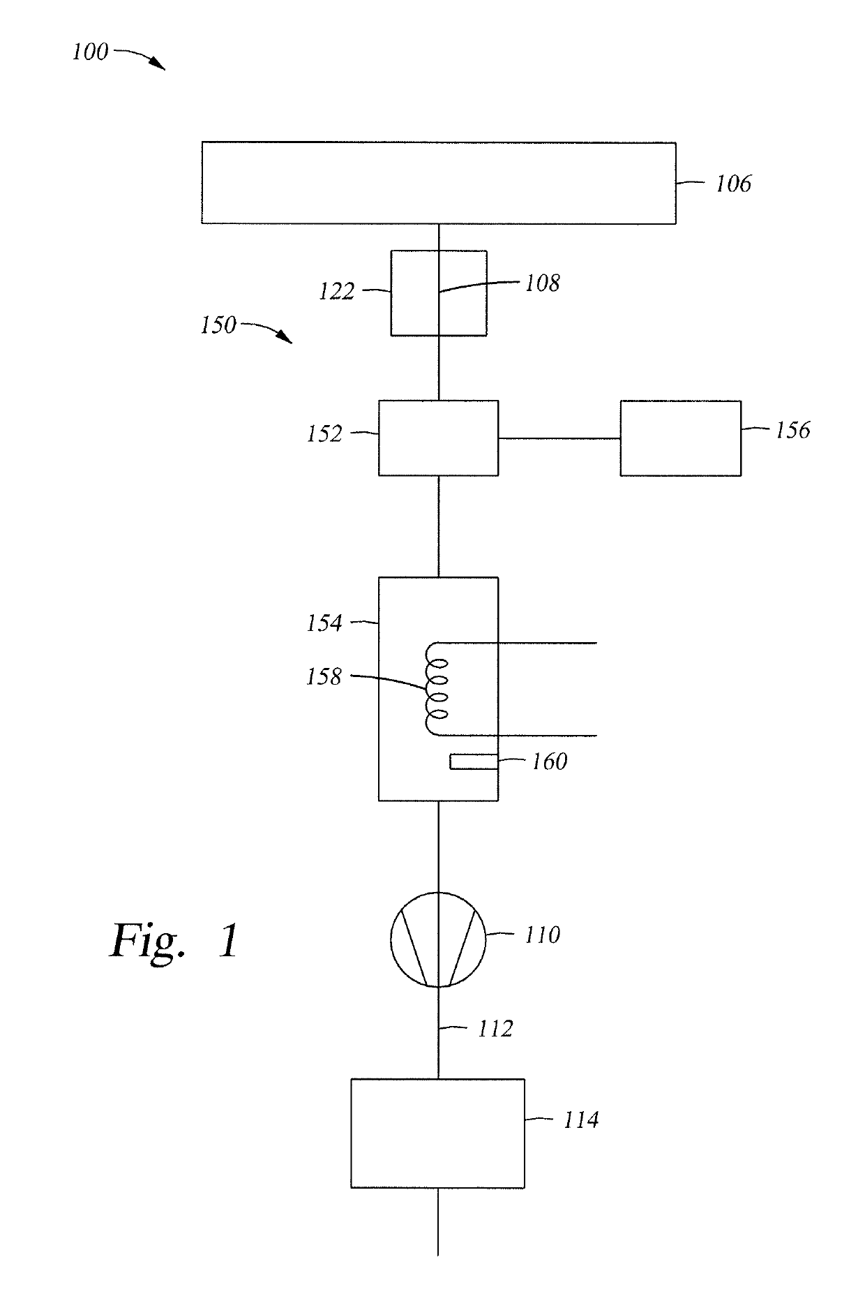
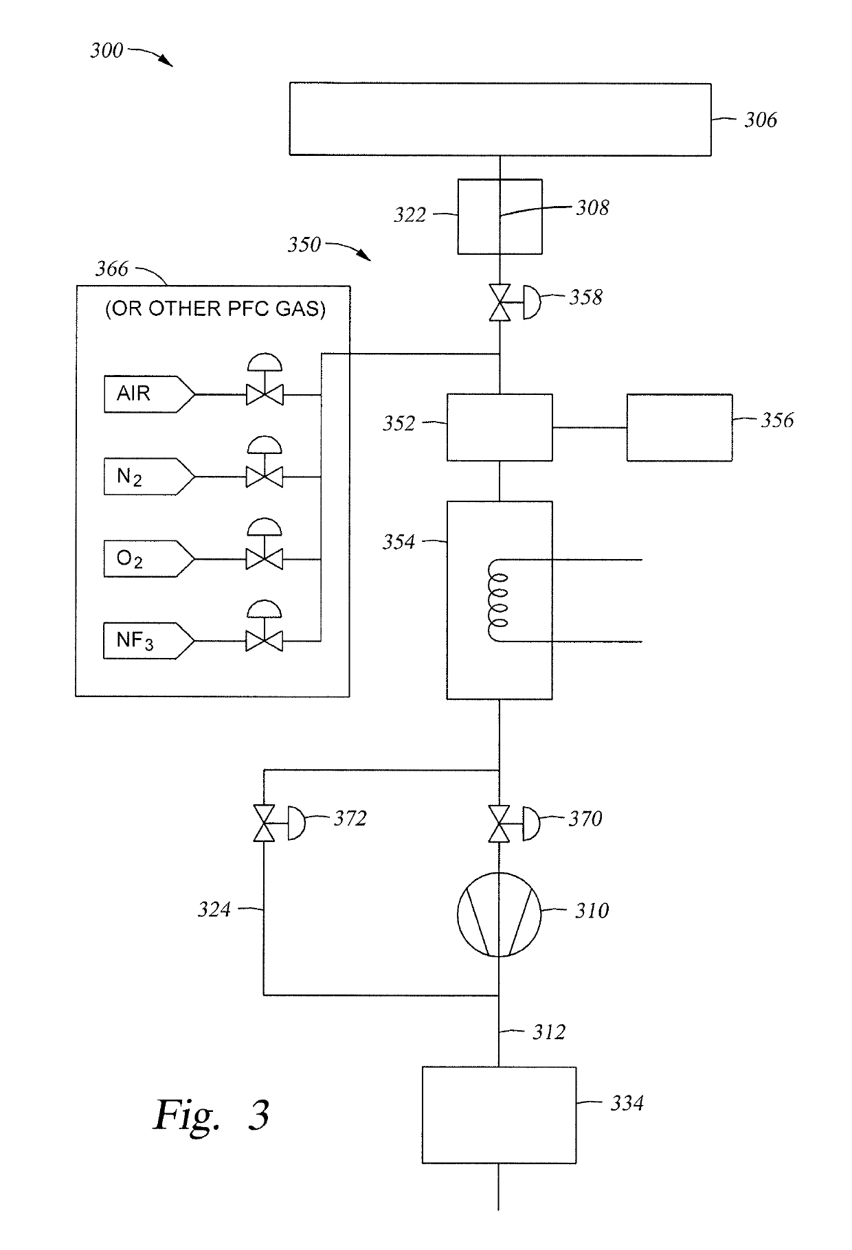
[0021]A foreline plasma reactor subsystem and methods for treating exhaust of a vacuum processing system are provided. The foreline plasma reactor subsystems enable treatment of vacuum processing exhaust gases with reduced particulate accumulation and damage to vacuum pumps and downstream effluent handling equipment. For example, the foreline plasma reactor subsystem described herein treats exhaust gases such that the exhaust gases form particles in the foreline plasma reactor subsystem, where the particles are trapped, and form a reduced number of particles in downstream pumps, pipes, and other equipment.

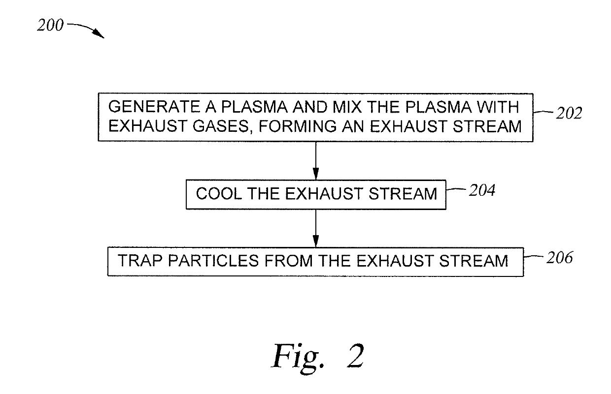
[0022]One embodiment disclosed herein generates a plasma, mixes the plasma with exhaust gases, cools the mixture of exhaust gases and plasma, and traps particles formed from the mixture of exhaust gases and plasma. The plasma heats the exhaust gases and may react with the exhaust gases to form other substances. Cooling the mixture of exhaust gases and plasma may cause gases to cond...


PUM

PropertyMeasurementUnit
purityaaaaaaaaaa
volatileaaaaaaaaaa
temperatureaaaaaaaaaa

Abstract

The present disclosure relates to methods and apparatus for treating vacuum processing system exhaust gases. In addition, methods and apparatus for maintenance of foreline plasma reactor subsystems are disclosed. In some embodiments, an apparatus for treating an exhaust gas in a foreline of a vacuum processing system includes a plasma source coupled with a foreline of a process chamber, a treatment agent source coupled with the plasma source, and a downstream trap to cool an exhaust stream and trap particles in the exhaust stream. In some embodiments, multiple foreline plasma reactor subsystems are used with a vacuum processing system, and one foreline plasma reactor subsystem can be isolated and maintained (e.g., cleaned) while exhaust gas treatment continues in another foreline plasma reactor subsystem and processing continues in the vacuum processing system.

Description

CROSS-REFERENCE TO RELATED APPLICATIONS[0001]This application is a continuation of U.S. application Ser. No. 14 / 630,631 filed Feb. 24, 2015, which claims benefit of U.S. provisional application Ser. No. 61 / 949,217, filed Mar. 6, 2014, which is herein incorporated by reference.BACKGROUNDField[0002]Embodiments of the present disclosure generally relate to vacuum processing techniques. More particularly, embodiments of the present disclosure relate to a system for controlling reactions and condensation of exhaust gases from a vacuum processing system and cleaning methods for the same system.Description of the Related Art[0003]The flat panel display and semiconductor industries, as well as other industries, use vacuum processing (e.g., chemical vapor deposition (CVD)) techniques to produce high-purity solid materials. The process is often used to produce thin films. In many vacuum processing techniques, the substrate (e.g., a wafer) is exposed to one or more volatile precursor gases (i....

Claims


Application Information

Patent Timeline
Patent Type & Authority Applications(United States)
IPC IPC(8): C23C16/44H01J37/32
CPCC23C16/4412C23C16/4405H01J37/32834H01J37/32844Y02C20/30
Inventor DICKINSON, COLIN JOHN
Owner APPLIED MATERIALS INC
Why Eureka
Try Eureka