Testing facility for ageing exhaust gas systems

a technology of exhaust gas system and testing facility, which is applied in the direction of exhaust gas recirculation, exhaust treatment, structural/machine measurement, etc., can solve the problems of ash-forming components oxidizing or degenerating, extremely small diameter, and ash turning into ash, so as to increase the significance of measured values and simplify the effect of regulation

Active Publication Date: 2019-08-01
FEV EURO GMBH
View PDF0 Cites 2 Cited by
  • Summary
  • Abstract
  • Description
  • Claims
  • Application Information

AI Technical Summary

Benefits of technology

[0019]A broad invariability of this value is assumed, in particular with a deviation of + / −20% and preferably a max. + / −10% of the lambda value. The second inflow is, in particular, a separate inflow system. This can be formed by exhaust gas and / or fresh air and / or a mixture of these or other gases. Thus, regulation is simplified to the extent that, for regulating the burner combustion, the control values do not have to be adapted, or only little adapted, in the event of a change of the inflow of ash-forming component, which increases the significance of the measured values. When using exhaust gas recirculation, the recirculated exhaust gas already has the desired lambda value. This can be 1 in particular in the case of Otto-cycle engine applications. A region of 1+ / −10% is advantageous here. For diesel systems (inter alia DPF), a λ>1 is preferably selected according to the vehicle operation (by way of example between 1.2 and 2).
[0020]It is further advantageous if, during a measuring cycle of the ageing of a particulate filter, an ash-forming component is supplied via an ash-forming component inflow, and to terminate the measuring cycle the ash-forming component inflow is flushed with a medium which does not have a tendency to become ash. This medium can be, by way of example, a simple alcohol which can release ash-forming components deposited on the walls of the inflow and lead them to combustion, or a gas, such as for example ambient air or exhaust gas. In each case it is advantageous if the ash-forming component is removed from the ash-forming component inflow, such as by way of example is blown out, since after terminating the measuring cycle the temperature of the burner is still extremely high for a longer time, and the ash-forming component could still turn to ash in its inflow.

Problems solved by technology

When the ash-forming component is fed into the burner flame, the feed pipe of the ash-forming component is consequently exposed in part inside the insulation and thus to continuously high burner temperatures, which can lead to the ash-forming component oxidizing or degenerating, such as for example turning to ash, already inside its feed pipe.
These specifications mean that the diameter is extremely small.

Method used


Image

  • Testing facility for ageing exhaust gas systems
  • Testing facility for ageing exhaust gas systems

Examples


example a

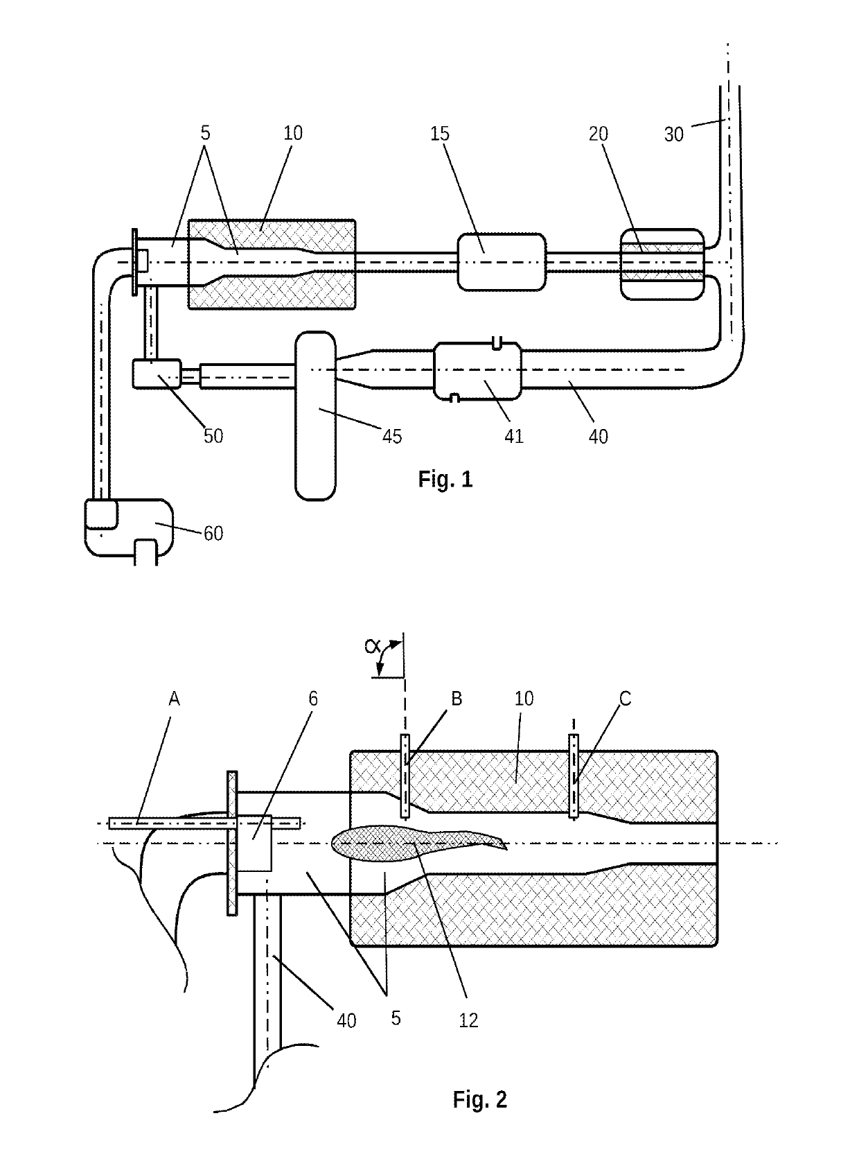
[0029 can be advantageous since the ash-forming component is injected into the cold region of the burner 5 and thus the danger of carbonization in the ash-forming component inflow itself, such as for example through deposits on the inside wall or nozzle thereof, is minimized. The example B, supply inflow into the flame, can be preferred since the ash-forming component is oxidized immediately and substantially completely and converted into ash with great reliability. Equally, injection can take place after the flame 12 (see Example C) since it is here again somewhat cooler. Where applicable, an additional after-burn can be required.

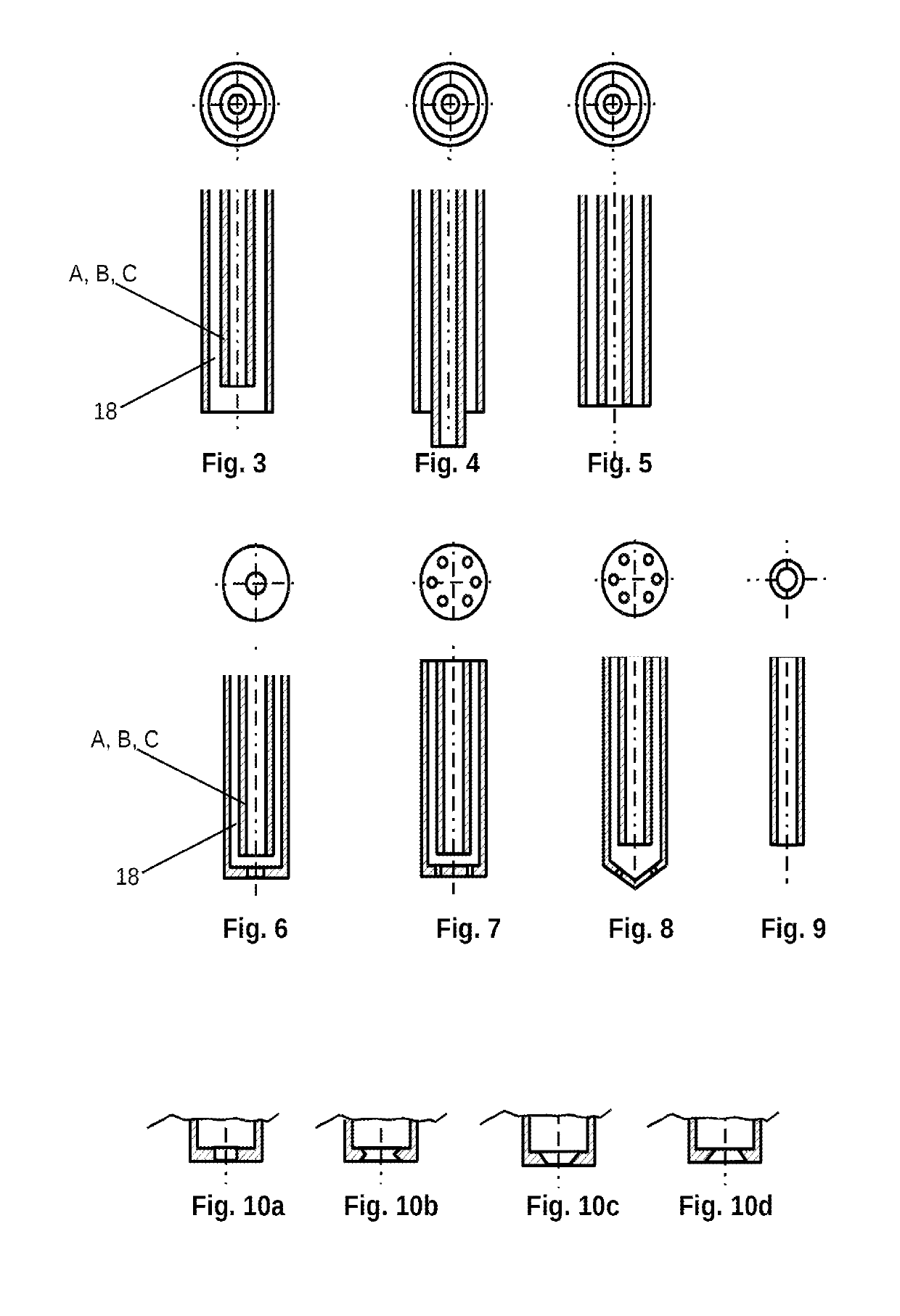
[0030]FIGS. 3 to 9 show different nozzles wherein the corresponding nozzle is shown in a view from below in the upper part of each figure. FIG. 9 shows the simplest case already mentioned where the ash-forming component inflow is designed only as a pipe with an open blunt end. This design is particularly suitable at position A since here no high temperatur...


PUM


Abstract

Testing facility for ageing exhaust gas systems, with a burner (5), a receiving area for receiving at least one catalytic converter (15) and/or a particulate filter (20). An ash-forming component is supplied here to the burner flame.

Description

CROSS-REFERENCE TO RELATED APPLICATIONS[0001]This Application claims priority from Application 102018102104.6 filed on Jan. 31, 2018 in Germany.FIELD OF THE INVENTION[0002]The present invention relates to a testing facility for ageing exhaust gas systems and to a method for operating testing facilities.BACKGROUND OF THE INVENTION[0003]In the development of exhaust gas trains for motor vehicles it is an important task to test the exhaust gas trains in order, with the testing facility, to simulate a desired service life of the exhaust gas train over a shortened test period and in order to thus obtain measured values which have a real significance in relation to the actual service life of the exhaust gas train. At the moment, great weight is placed on the simulation of the service life of particulate filters. From WO2010022747A1 a testing unit is known FOR the ageing of catalytic converters.SUMMARY OF THE INVENTION[0004]A testing facility for the ageing of exhaust gas systems comprises...

Claims


Application Information

Patent Timeline
Patent Type & Authority Applications(United States)
IPC IPC(8): F01N11/00F01N13/00G01M15/10
CPCF01N11/00F01N13/009G01M15/102F01N3/021F01N3/025F01N3/2033F01N2240/14F01N2550/02F02M26/15Y02T10/12F01N9/00G01M15/10G01M99/00
Inventor STERLEPPER, STEFANCOX, JIMMY
Owner FEV EURO GMBH
Why Eureka
Try Eureka