
Automated fabrication of layer-by-layer tissue engineered complex tubes

a tissue engineered complex, layer-by-layer technology, applied in the direction of prosthesis, blood vessels, other domestic articles, etc., can solve the problems of not meeting the physiological requirements of sdbv, posing a serious risk of myocardial infarction, and resting ,

Active Publication Date: 2020-06-23
UNIV DE LOS ANDES +5
View PDF1 Cites 2 Cited by
  • Summary
  • Abstract
  • Description
  • Claims
  • Application Information

AI Technical Summary

Benefits of technology

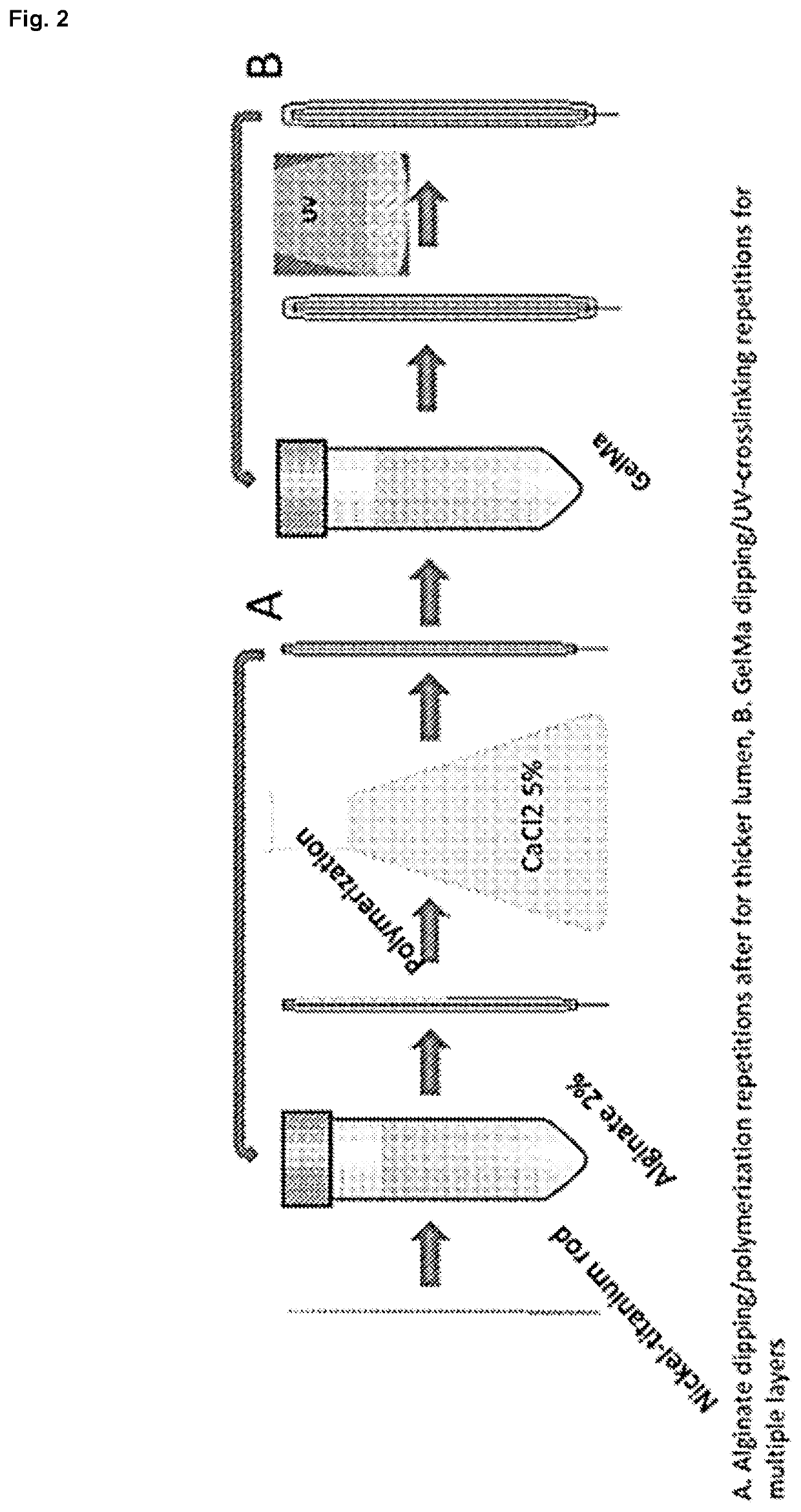
The present invention is a versatile method for making multilayer hollow tubes using a layer-by-layer rod dipping approach. This method allows for fine control over various fabrication parameters, such as ascending / descending speeds, rod rotational velocity, and crosslinking or polymerization time. This technique can generate more complex structures, such as vessel-like structures, urethral grafting, and prostate grafting. Additionally, the invention describes a novel method of incorporating cells directly into the matrix, which can be carried out using an automatized system. This method can control the material composition, geometry, and spatial location of cells and biomaterials, resulting in well-controlled biological and mechanical properties. The finished tubes or vessels maintain their structure, geometry, and integrity.

Problems solved by technology

Coronary arteries are small diameter blood vessels (SDBV), on average 4 mm in diameter, and once occluded, they pose a serious risk for myocardial infarction.
A stent is typically deployed to open-up the narrowed vessel; however, restenosis may occur, necessitating replacement of the vessel.
Whereas large diameter blood vessels are readily substituted with Teflon or other synthetic-based constructs, they fall short of meeting the physiological requirements for SDBV, and are only replaced with an autologous graft.
Nevertheless, this alternative increases the risk of comorbidity and the patients can go through several rounds of surgical procedures.
These autografts, although mechanically inferior, provide a blood-compatible vessel solution.
However, limited availability and donor site comorbidity are major points of concern for employing an autograft for SDBV.
On the other hand, differences in diameter and compliance to the natural vessels in the anastomosis area might lead to intimal hyperplasia and failure of the graft.
However, it has neither been explored to generate more complex multilayer vessel-like structures nor used to fabricate cell-laden concentric layers.
By automatizing the fabrication of tissue engineered SDBV it is possible to dramatically increase the production volume and decrease sample-to-sample variability, which can confound results and reduce the project's success and medical translation.

Method used


Image

  • Automated fabrication of layer-by-layer tissue engineered complex tubes
  • Automated fabrication of layer-by-layer tissue engineered complex tubes
  • Automated fabrication of layer-by-layer tissue engineered complex tubes

Examples


example 1

[0064]Robotic Device

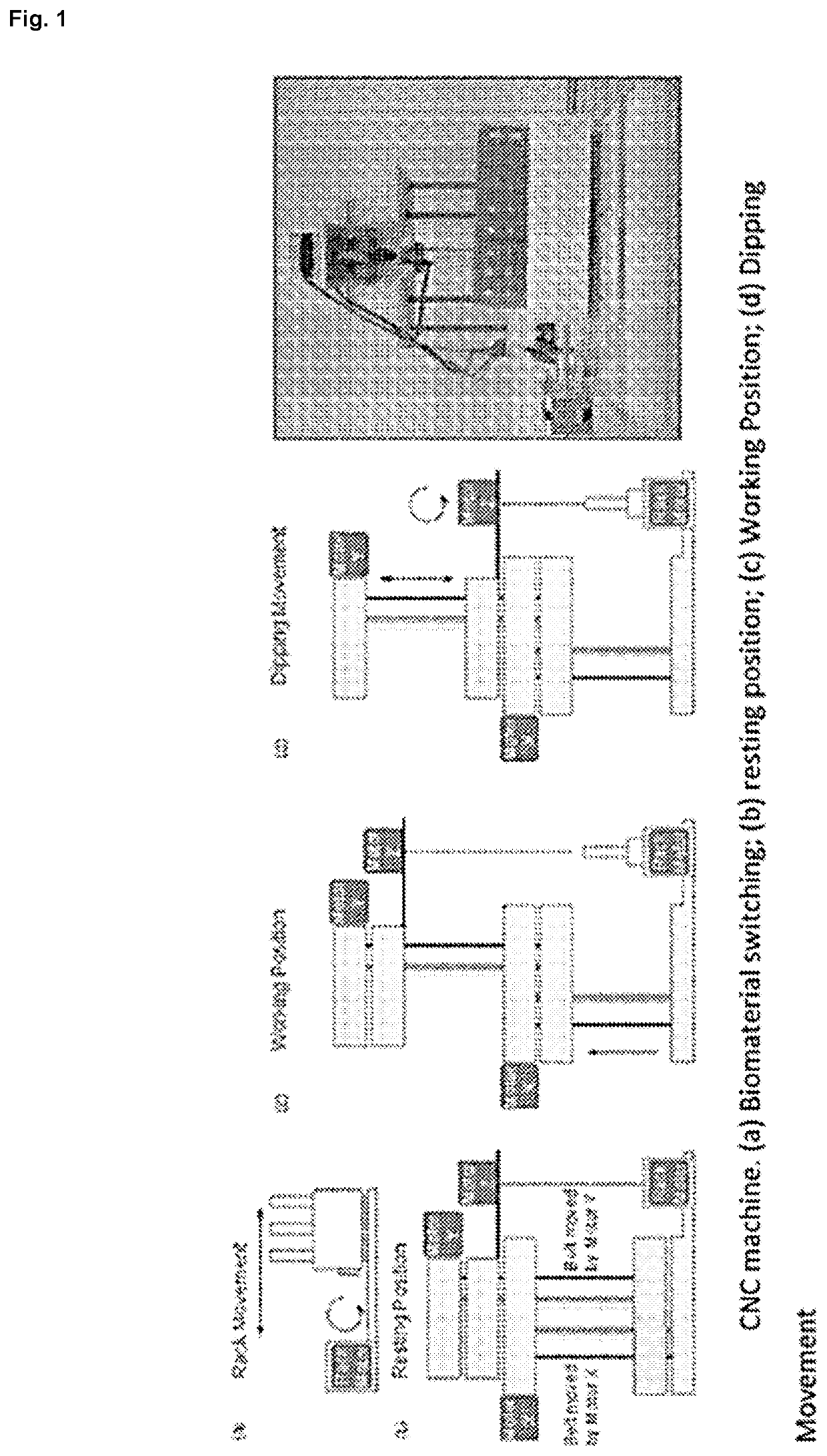
[0065]A computerized numerical control (CNC) machine that allows the controlled elevation, drop and rotation of a metal mandrel was designed and constructed in our laboratory and it is illustrated in FIG. 1. The robot consists of several platforms that can slide vertically, guided by steel rod, and moved by pulleys, belts and 2 NEMA 16 stepper motors (SM-42BYG011-25, Mercury Motor, China). The first motor, denominated as Motor X, allows the system to go from rest position (FIG. 1(b)) to working position (FIG. 1(c)); whereas the second motor, Motor Y, controls the mandrel dipping while the rotational movement is performed by a third NEMA 16 stepper motor, Motor Z, shown in FIG. 1(d).

[0066]Motors are controlled by an electronic circuit using different Open Source elements. The hardware consists of an Arduino UNO R3 microprocessor (50, Adafruit, USA) connected to a gShield v.5 (1750, Adafruit) specially designed to allow easy control of 3 bipolar stepper motors simu...

example 2

Robotic Device (as Described in Example 1)

Preparation of GeIBMa-Alginate Solution.

[0109]Methacrylated bovine gelatin, or GeIBMa, was synthesized by mixing bovine gelatin (Bloom 220, Rousselot, Netherlands) and methacrylic anhydride to a final concentration of 8% (v / v) as previously dissolved in PBS 1× (pH 7.4) at 60° C. for 3 hrs. as previously described (Nichol et al. 2010; Van Den Bulcke et al. 2000). Three stock solutions were prepared. GeIBMa stock solution was prepared by dissolving freeze dried GeIBMa in PBS 1× at 40° C. at a concentration of 20% (w / v). Alginate stock solution was prepared by dissolving medium viscosity sodium alginate (A2033, Sigma, USA) in PBS 1× at 60° C. at a concentration of 2% (w / v). The PI stock solution was prepared by dissolving 2-Hydroxy-4′-(2-hydroxyethoxy)-2-methylpropiophenone (410896, Sigma, USA) in PBS 1× at 85° C. until fully dissolved. The GeIBMa-alginate solution was prepared by mixing the three stock solutions to a final concentration on 10%...


PUM

PropertyMeasurementUnit
angleaaaaaaaaaa
angleaaaaaaaaaa
diameteraaaaaaaaaa

Abstract

The present invention overcomes all the above drawbacks and provides a versatile method for the fabrication of multilayer hollow tubes that uses a layer-by-layer rod dipping approach using different biomaterials. The device enables fine control over fabrication parameters, such as ascending / descending speeds, rod rotational velocity, and crosslinking or polymerization time. All these technologies allows the generation of more complex multilayer hollow tubes such as vessel-like structures, urethral grafting, prostate grafting and the like.

Description

TECHNICAL FIELD[0001]The present invention relates to multilayer hollow tubes and method of productions thereof. The multilayer hollow tubes of the present invention can be produced easily and rapidly and, moreover, present structural configurations that would mimic the one observed in the natural body. Therefore, they can be used in various biomedical applications.BACKGROUND[0002]In 2012 over 15 million people in the United States were diagnosed with coronary heart disease and it is currently the leading cause of death. Coronary arteries are small diameter blood vessels (SDBV), on average 4 mm in diameter, and once occluded, they pose a serious risk for myocardial infarction. A stent is typically deployed to open-up the narrowed vessel; however, restenosis may occur, necessitating replacement of the vessel. Whereas large diameter blood vessels are readily substituted with Teflon or other synthetic-based constructs, they fall short of meeting the physiological requirements for SDBV,...

Claims


Application Information

Patent Timeline
Patent Type & Authority Patents(United States)
IPC IPC(8): B29C41/22A61L27/50A61L27/34B29C41/14A61L27/38A61F2/04A61F2/06A61L27/18A61L27/20A61L27/22A61L27/26A61L27/36A61L27/54A61L27/58B32B1/08B32B9/02B29L31/00
CPCA61L27/3813A61L27/3834A61L27/3882A61L27/3817C08L67/04B32B9/02A61L27/20A61F2/04A61L27/3808A61L27/3679A61L27/34A61L27/58B32B1/08A61F2/06A61L27/18A61L27/507A61L27/3826B29C41/22A61L27/54C08L89/06B29C41/14A61L27/222A61L27/26A61L2300/64A61L2430/32A61L2300/604A61L2420/08A61F2002/047A61L2300/608A61L2420/02B32B2535/00B29K2089/00A61F2240/001A61F2210/0076A61L2430/22B29L2031/7534
Inventor ACEVEDO, JUAN PABLOWILKENS, CAMILAKHOURY, MAROUNRIVET
Owner UNIV DE LOS ANDES
Learn More