Wireless high power transfer

a high-power transfer and wireless technology, applied in the direction of electric vehicles, charging stations, transportation and packaging, etc., can solve the problem of reducing the power to be handled per secondary resonating circuit, and achieve the effect of improving flux and power sharing

Active Publication Date: 2019-08-29
DELTA ELECTRONICS (THAILAND) PUBLIC CO LTD
View PDF0 Cites 5 Cited by
  • Summary
  • Abstract
  • Description
  • Claims
  • Application Information

AI Technical Summary

Benefits of technology

[0039]Generally, it is possible to arrange the symmetry winding of a particular resonating circuit on a different core part of the secondary magnetic core structure than the winding of the resonating inductor of a resonating path, as long as the magnetic flux through that core part is representative of or corresponds to the magnetic flux through the section including the winding of the resonating inductor. But in order to achieve a better flux and power sharing, the symmetry winding is preferably wound on the same section of the secondary magnetic core structure as the winding of the res

Problems solved by technology

This reduces the power to be handled per secondary resonating circ

Method used


Image

  • Wireless high power transfer
  • Wireless high power transfer
  • Wireless high power transfer

Examples


Embodiment Construction

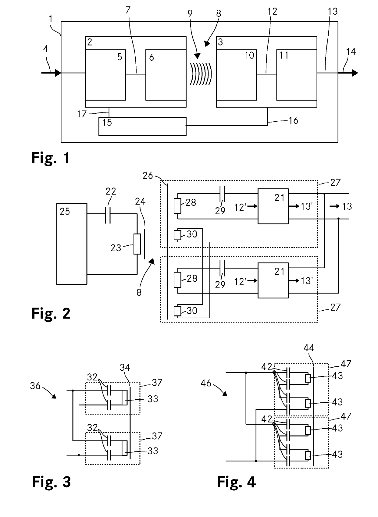
[0079]FIG. 1 shows a schematic representation of a first embodiment of a wireless power transfer arrangement 1 according to the invention. The wireless power transfer arrangement 1 includes a primary side 2, a secondary side 3 and a controller 15. The primary side 2 includes an input stage 5 for converting an input power 4 into an AC primary output power 7 which is fed to a primary resonator 6. The primary resonator 6 induces a magnetic field 9 to wirelessly transmit power across an airgap 8. The secondary side 3 includes a secondary resonator 10 which picks up the magnetic field 9 and converts the power received through the magnetic field 9 into an AC secondary output 12. An output stage 11 is connected to the secondary resonator 10 and converts the AC secondary output 12 to a DC secondary output 13 which is then provided at an output of the wireless power transfer arrangement 1 as an output power 14.

[0080]The controller 15 controls the power transfer from the primary side 2 to the...


PUM


Abstract

In a system for wirelessly transferring power from a primary side across an airgap to a secondary side, the secondary side includes two parallel resonating circuits (27) each including two parallel resonating paths with a series connection of a resonating inductor (28), and a resonating capacitor 29. A rectifier (21) is connected to the output of each resonating path for converting the AC output (12′) of the resonating paths to a DC output (13′). The outputs of the rectifiers (21) are connected in parallel to provide the AC output power (13) to a load such as a battery or the like. Each resonating path further includes a symmetry inductance connected in series to improve current sharing among the resonating paths and to reduce the higher harmonic portion in the resonating paths. For balancing the flux each resonating circuit 27 includes in a preferred embodiment of the invention a symmetry winding (30) wound on the same core as the resonating inductor 28 of that resonating path where all symmetry windings (3) are connected in parallel to ensure optimal flux sharing.

Description

TECHNICAL FIELD[0001]The invention relates to a wireless power transfer arrangement for wirelessly transferring power from a primary side across an airgap to a secondary side by inductive coupling, wherein the primary side includes an input stage for converting an input power to an AC primary output power and a primary resonator for receiving the AC primary output power and inducing a magnetic field and wherein the secondary side includes a secondary resonator for converting the power received through the magnetic field to an AC secondary output power and an output stage for converting the AC secondary output power to a DC secondary output power. The invention further relates to a secondary side for such a wireless power transfer arrangement and a method for wirelessly transferring power from a primary side across an airgap to a secondary side.BACKGROUND ART[0002]Electrical energy is used in many different applications. To power electrically driven devices, items or objects that are...

Claims


Application Information

Patent Timeline
IPC IPC(8): H02J50/12H01F38/14H01F27/245H01F27/28H02J7/02B60L53/122
CPCH02J50/12H01F38/14B60L53/122H01F27/28H02J7/025H01F27/245H02J50/402H02J50/70B60L53/12B60L2200/42B66B7/00Y02T10/70Y02T90/14Y02T10/7072
Inventor RICHTER, ULRICH
Owner DELTA ELECTRONICS (THAILAND) PUBLIC CO LTD
Why Eureka
Try Eureka