
Closed-loop fluid control to obtain efficient machining

Active Publication Date: 2019-09-12
RAYTHEON TECH CORP
View PDF6 Cites 4 Cited by
  • Summary
  • Abstract
  • Description
  • Claims
  • Application Information

AI Technical Summary

Benefits of technology

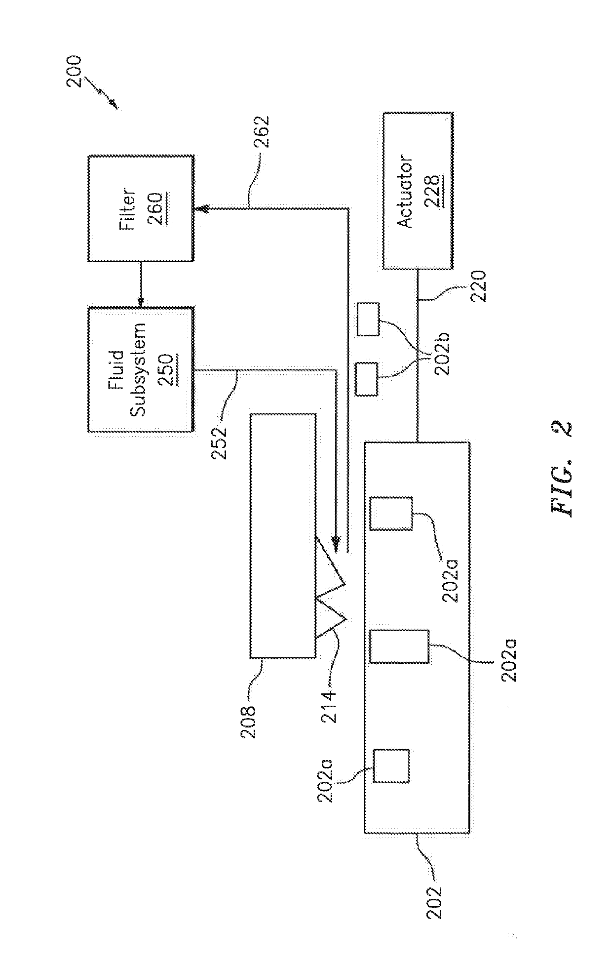
The patent describes a system and method for adjusting the fluid supplied to a cutting tool of a machine tool based on the load on the tool. The system includes a machine tool with a cutting tool, a fluid subsystem that provides fluid to the cutting tool, and a controller that adjusts the state of the device in the fluid subsystem based on signals indicative of the load on the cutting tool. The system can adjust the state of the device based on the material of the workpiece, the material of the cutting tool, the type of fluid, the spindle speed, the chip load, the cutting depth, the orientation of the cutting edge, and the cutting speed. The method involves delivering fluid to the cutting tool, obtaining a signal indicative of the load on the tool, adjusting the state of the device in the fluid subsystem based on the signal, and repeating the process for different loads. The technical effect of the patent is to improve the efficiency and accuracy of the cutting process by optimizing the fluid supply based on the load on the tool.

Problems solved by technology

Even though the application of cutting fluids helps in terms of cooling and lubricating tools, the application of cutting fluid is accompanied by significant cost.
For example, a continuous stream of cutting fluid during machining consumes enormous quantities of power and fluid.
Although some of the cutting fluids may be recycled, the machining procedure still ends up consuming a large volume of cutting fluids; as such, a large capital investment associated with procurement, storage and handling of cutting fluids is required.
This cost does not account for risks to which operators are exposed when using these fluids.
Another issue encountered in machining operations deals with thermal shock.
As a cutting edge of a tool engages a workpiece and a material (e.g., a chip) of the workpiece is liberated during a first cutting operation, friction between the cutting edge and the material of the workpiece causes the cutting edge to get hot almost immediately.
Thermal shock causes fatigue of the cutting edge.
However, the techniques are less effective in providing cooling / lubrication to a cutting tool and evacuating cutting chips.
The reduced cooling / lubrication results in a build-up of work material (e.g., chips) on the cutting edge of the tool, and consequently causes tool wear, thermal distortion of machined parts, re-cutting chips, and some other undesirable effects.
Thus, dry-cutting and MQL have their own limitations, especially in conjunction with aerospace components that frequently include heat-resistant, high-strength alloys.

Method used


Image

  • Closed-loop fluid control to obtain efficient machining
  • Closed-loop fluid control to obtain efficient machining
  • Closed-loop fluid control to obtain efficient machining

Examples


Embodiment Construction

[0024]It is noted that various connections are set forth between elements in the following description and in the drawings (the contents of which are included in this disclosure by way of reference). It is noted that these connections are general and, unless specified otherwise, may be direct or indirect and that this specification is not intended to be limiting in this respect. A coupling between two or more entities may refer to a direct connection or an indirect connection. An indirect connection may incorporate one or more intervening entities.

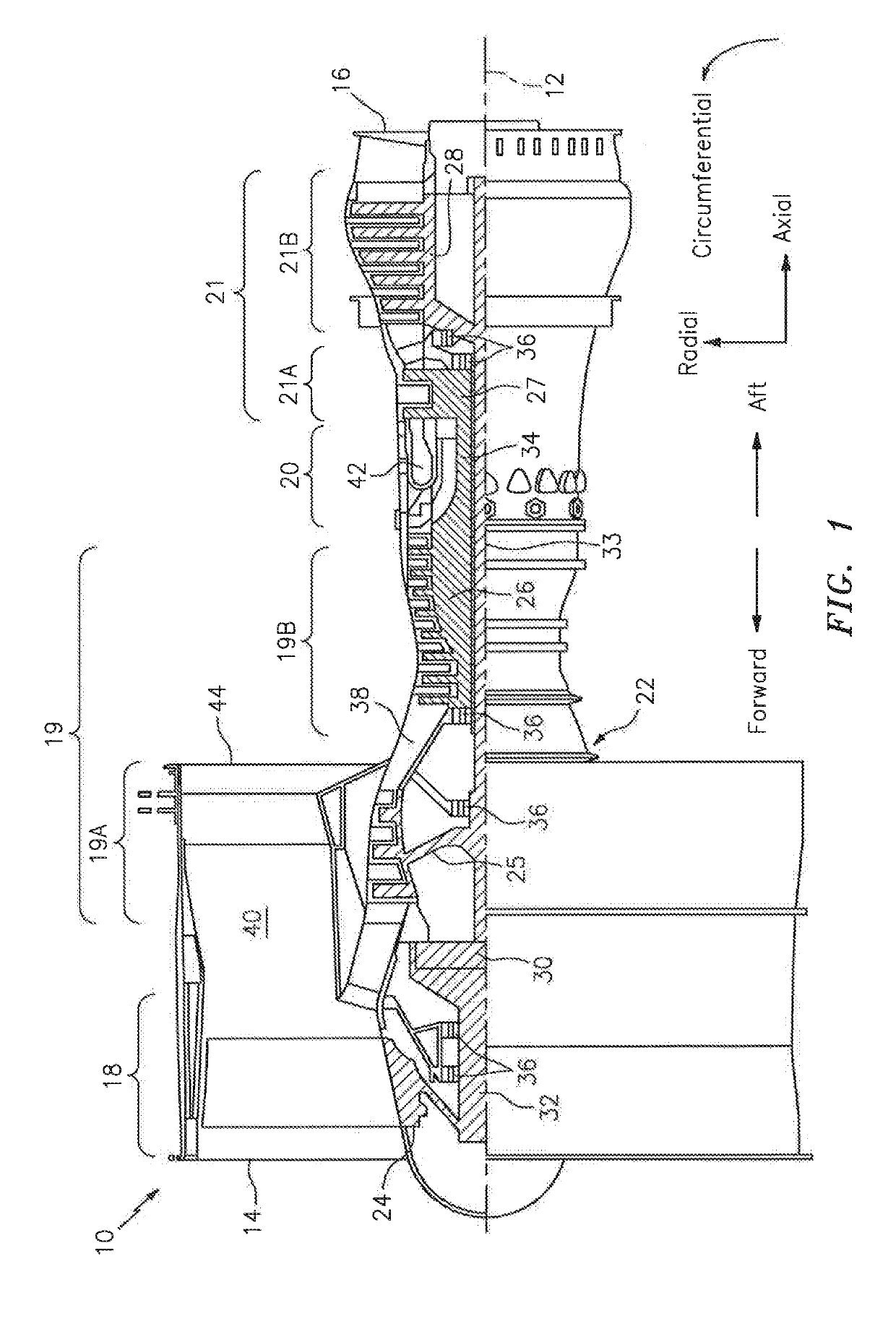
[0025]Aspects of the disclosure may be applied in connection with a gas turbine engine. FIG. 1 is a side cutaway illustration of a geared turbine engine 10. This turbine engine 10 extends along an axial centerline 12 between an upstream airflow inlet 14 and a downstream airflow exhaust 16. The turbine engine 10 includes a fan section 18, a compressor section 19, a combustor section 20 and a turbine section 21. The compressor section 19 inc...


PUM


Abstract

A system includes a machine tool that includes a cutting tool, a fluid subsystem that provides fluid to the cutting tool, and at least one processor that executes instructions that cause the at least one processor to: obtain a signal indicative of a load on the cutting tool, establish a first value of at least one parameter of the fluid based on the signal, obtain a second value of the at least one parameter that is based on a simulation, determine a difference between the first value and the second value, and adjust a state of a device of the fluid subsystem based on the determined difference.

Description

BACKGROUND[0001]Machine tools, such as for example computer numerical controlled (CNC) machine tools, have been utilized in many industries. Such machines may be used, for example, to manufacture complex / intricate metal components. Cutting fluids are frequently used as part of a machining procedure. Cutting fluids cool and lubricate cutting tools of a machine tool, thereby extending the operational lifetime of the tools. In addition to enhanced tool life, a particular formulation of a cutting fluid may increase / enhance a quality of a surface finish of a workpiece and reduce friction between a tool and the workpiece.[0002]In a typical manufacturing environment, a coolant system applies cutting fluids with a constant flow rate, e.g., a heavy and continuous jet / stream of cutting fluid is applied to a cutting zone (where the cutting zone corresponds to the interface between a tool and a workpiece). As discussed above, the applied cutting fluids provide cooling and / or lubrication of the ...

Claims


Application Information

Patent Timeline
IPC IPC(8): B23Q11/10B23Q11/12B23Q17/00F16N29/02
CPCB23Q11/12F16N2250/04F16N2270/20B23Q11/1038F16N2250/40G05B2219/49043F16N29/02B23Q17/007B23Q11/1046B23Q17/0961Y02P70/10
Inventor WANG, ZHIGANGGUO, CHANGSHENGVIENS, DANIEL V.
Owner RAYTHEON TECH CORP
Learn More