GRATING DEVICE, LIGHT-EMITTING UNIT and LIGHT DETECTION METHOD

a light-emitting unit and grating technology, applied in the field of grating devices and light-emitting units, can solve the problems of narrow wavelength range only being translated to narrow or moderate angle range, conventional lidar needs an expensive opto-mechanical system to enlarge the detection range, and achieve the effect of enhancing the intensity of reflected beams

Inactive Publication Date: 2019-10-17
WANG QIANG
View PDF25 Cites 2 Cited by
  • Summary
  • Abstract
  • Description
  • Claims
  • Application Information

AI Technical Summary

Benefits of technology

[0052]Preferably, the lidar system further comprises a lens between the optical detection unit and the object, configured to enhance the intensity of the reflected beams.

Problems solved by technology

A conventional lidar needs an expensive opto-mechanical system to enlarge a detection range.
However, it is difficult to integrate opto-mechanical elements such as a mirror in a chip.
One drawback of the wavelength tuning is that a broad wavelength range can only be translated to a narrow or moderate angle range.
It is challenging for the TLS to provide a broad wavelength range.

Method used


Image

  • GRATING DEVICE, LIGHT-EMITTING UNIT and LIGHT DETECTION METHOD
  • GRATING DEVICE, LIGHT-EMITTING UNIT and LIGHT DETECTION METHOD
  • GRATING DEVICE, LIGHT-EMITTING UNIT and LIGHT DETECTION METHOD

Examples


first embodiment

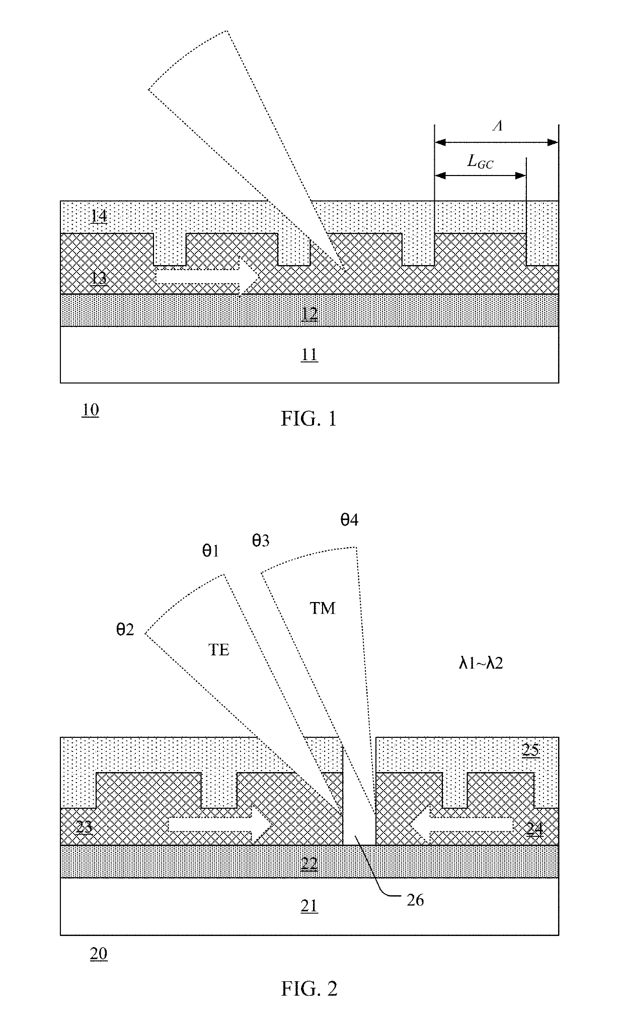
[0082]FIG. 2 is a cross-sectional view showing a grating device according to the present disclosure. The grating device 20 includes a substrate 21, a blocking layer 22 on the substrate 21, a first waveguide 23 and a second waveguide 24 on the blocking layer 22, and a cladding layer 25 on the first waveguide 23 and the second waveguide 24. Preferably, the grating device 20 further includes a gap 26 which separates the first waveguide 23 from the second waveguide 24.

[0083]The substrate 21 may be made of silicon, on which semiconductor devices such as transistors may also be formed. Thus, the grating device may be integrated with a signal processing circuit as a single lidar chip.

[0084]The blocking layer 22 may be formed between the substrate 21 and the first waveguide 23 and the second waveguide 24 so as to confine a laser beam to propagate through the first waveguide 23 and the second waveguide 24. The blocking layer is made of, for example, silicon oxide.

[0085]Each of the first wave...

second embodiment

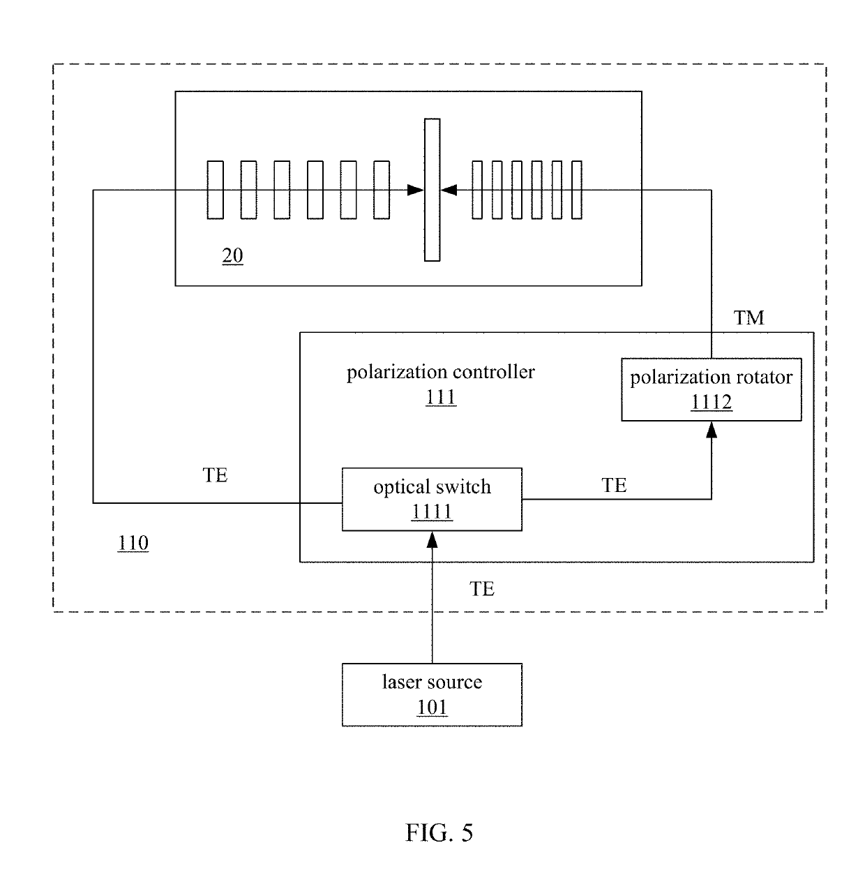
[0103]FIG. 5 is a cross-sectional view showing a light-emitting unit according to the present disclosure. A light-emitting unit 110 includes a grating device 20 and a polarization controller 111.

[0104]The grating device 20 has a structure shown in FIG. 2, and includes a first waveguide 23 and a second waveguide 24.

[0105]A laser source 101 may generate a source beam of a TE mode, as a first input beam. The polarization controller 111 generates a second input beam of a TM mode from the source beam. Moreover, the polarization controller 111 may select one of the first and second input beams.

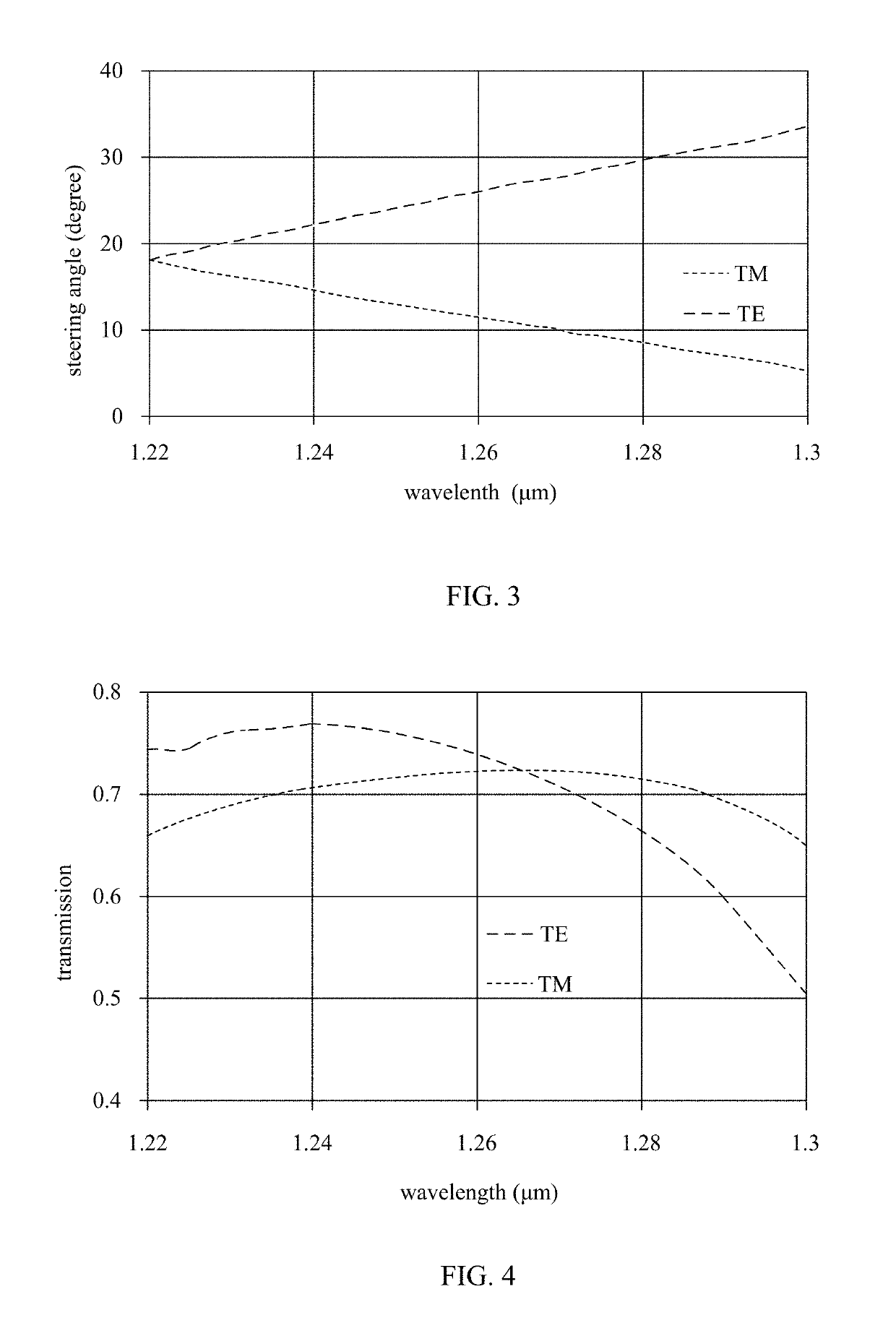
[0106]The grating device 20 is coupled to the polarization controller 111 laser. The first waveguide 23 receives the first input beam of the TE mode, and the second waveguide 24 receives the second beam of the TM mode. Two output beams are generated by steering the first and second input beams by diffraction respectively, with different steering angles, at least, at one wavelength.

[0107]In this embo...

third embodiment

[0110]FIG. 6 is a cross-sectional view showing a light-emitting unit according to the present disclosure. A light-emitting unit 210 includes a plurality of grating devices 20, a polarization controller 111, a first beam splitter 211, and a second beam splitter 212.

[0111]The plurality of grating devices 20 are aligned in an array, and preferably, share a common substrate and a common blocking layer in a single chip. Each of the plurality of grating devices 20 has a structure shown in FIG. 2, and includes a first waveguide 23 and a second waveguide 24.

[0112]A laser source 101 may generate a source beam of a TE mode, as a first input beam. The polarization controller 111 generates a second input beam of a TM mode from the source beam. Moreover, the polarization controller 111 may select one of the first and second input beams. The light source 101 and polarization controller 111 in the light-emitting unit according to the third embodiment are the same as those in the second embodiment,...


PUM

PropertyMeasurementUnit
wavelength rangeaaaaaaaaaa
widthaaaaaaaaaa
wavelengthsaaaaaaaaaa

Abstract

The present disclosure relates to a grating device, a light-emitting unit and a light detection method. The grating device includes a first waveguide and a second waveguide. A first input beam of a TE mode propagates through the first waveguide, and a second input beam of a TM mode propagates through the second waveguide. Output beams are obtained by diffraction which steer the first and second input beams. The first and second input beams have different steering angles at least at one wavelength. The grating device tunes a steering angle by varying a wavelength. The two input beams have different polarization modes, which increases an angle range of steering angles by wavelength tuning. A lidar using the grating device can expend an angle range of detection.

Description

CROSS REFERENCE TO RELATED APPLICATION(S)[0001]This application claims priority to U.S. provisional application Ser. No. 62 / 658360, filed on Apr. 16, 2018, which is incorporated herein by reference in its entirety.BACKGROUND OF THE DISCLOSUREField of the Invention[0002]The present disclosure relates to a lidar technology, and more particularly, to a grating device, a light-emitting unit and a light detection method.Description of the Related Art[0003]A lidar (light detection and ranging) has been widely used in the fields of autopilot, optical wireless communication, environmental topographic survey, and the like. Similar to a microwave radar, the lidar illuminates the object and detects a reflected light signal of the object, and processes the reflected light signal to obtain information about position and velocity of the object.[0004]A conventional lidar needs an expensive opto-mechanical system to enlarge a detection range. For example, a mirror may be used to steer a laser beam ...

Claims


Application Information

Patent Timeline
Patent Type & Authority Applications(United States)
IPC IPC(8): G01S7/499G02F1/313G01S7/481
CPCG02F2203/07G02F1/313G01S7/4814G01S7/499G02F2203/05G02F2203/24G01S7/4817G01S7/4818
Inventor WANG, QIANG
Owner WANG QIANG
Why Eureka
Try Eureka